Table of contents
Mixed Signal Simulation in ngspice
Keywords: Mixed Signal, ngspice, Verilog, RTL, d_cosim, Testbench
Digital simulation
-
The order of execution of events at the same time-step does not matter
-
The system is causal. Changes in the future do not affect signals in the past or the now
There are both commercial and open source tools for digital simulation. If you’ve never used a digital simulator, then I’d recommend you start with iverilog. I’ve made some examples at dicex.
Commercial
Open Source
Below is an example of a counter in SystemVerilog. The code can be found at counter_sv.
In the always_ff sections we code what will become our registers; combinatorial logic would go in an always_comb section.
module dig(
           input wire         clk,
           input wire         reset,
           output logic [4:0] b
           );

   logic                      rst = 0;

   always_ff @(posedge clk) begin
      if(reset)
        rst <= 1;
      else
        rst <= 0;
   end

   always_ff @(posedge clk) begin
      if(rst)
        b <= 0;
      else
        b <= b + 1;
   end // dig

endmodule
Transient analog simulation
Analog simulation is different. There is no quantized time step. How fast “things” happen in the circuit is entirely determined by the time constants, change in voltage, and change in current in the system.
It is possible to have a fixed time-step in analog simulation, for example, we say that nothing is faster than 1 fs, so we pick that as our time step. If we wanted to simulate 1 s, however, that’s at least 1e15 events, and with 1 event per microsecond on a computer it’s still a simulation time of 31 years. Not a viable solution for all analog circuits.
Analog circuits are also non-linear, properties of resistors, capacitors, inductors, diodes may depend on the voltage or current across, or in, the device. Solving for all the non-linear differential equations is tricky.
An analog simulation engine must parse spice netlist, and setup partial/ordinary differential equations for node matrix
The nodal matrix could look like the matrix below, $i$ are the currents, $v$ the voltages, and $G$ the conductances between nodes.
\[\begin{pmatrix} G_{11} &G_{12} &\cdots &G_{1N} \\ G_{21} &G_{22} &\cdots &G_{2N} \\ \vdots &\vdots &\ddots & \vdots\\ G_{N1} &G_{N2} &\cdots &G_{NN} \end{pmatrix} \begin{pmatrix} v_1\\ v_2\\ \vdots\\ v_N \end{pmatrix}= \begin{pmatrix} i_1\\ i_2\\ \vdots\\ i_N \end{pmatrix}\]The simulator, and devices model the non-linear current/voltage behavior between all nodes
as such, the $G$’s may be non-linear functions, and include the $v$’s and $i$’s.
Transient analysis use numerical methods to compute time evolution
The time step is adjusted automatically, often by proprietary algorithms, to trade accuracy and simulation speed.
The numerical methods can be forward/backward Euler, or the others listed below.
- Euler
- Runge-Kutta
- Crank-Nicolson
- Gear 1
If you wish to learn more, I would recommend starting with the original paper on analog transient analysis.
SPICE (Simulation Program with Integrated Circuit Emphasis) published in 1973 by Nagel and Pederson
The original paper has spawned a multitude of commercial, free and open source simulators, some are listed below.
If you have money, then buy Cadence Spectre. If you have no money, then start with ngspice.
Commercial
Free
Open Source
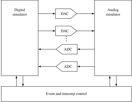
Figure 1: Mixed signal simulator, where a digital and an analog simulator exchange values through DAC and ADC connect modules under a shared event and timestep control
Demo
Tutorial at http://analogicus.com/jnw_sv_sky130a/
Repository at https://github.com/wulffern/jnw_sv_sky130a
Assumes knowledge of Tutorial
The circuit
In design/JNW_SV_SKY130A/JNWSW_CM.sch you’ll find a current mirror, and a 5-bit current DAC.
What we want from the digital is to control the binary value of the current DAC.
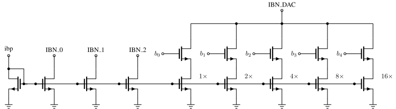
Figure 2: The JNWSW_CM schematic - a current mirror from ibp plus a 5-bit binary weighted current DAC controlled by b[4:0]
The digital code
The digital code is shown below. The clk controls the stepping, while the reset sets the output b=0. When reset is off, then the b increments.
module dig(
           input wire         clk,
           input wire         reset,
           output logic [4:0] b
           );

   logic                      rst = 0;

   always_ff @(posedge clk) begin
      if(reset)
        rst <= 1;
      else
        rst <= 0;
   end

   always_ff @(posedge clk) begin
      if(rst)
        b <= 0;
      else
        b <= b + 1;
   end // dig
endmodule
Compile RTL
The first thing we need to do is to translate the verilog into a compiled object that can be used in ngspice.
cd sim/JNWSW_CM
ngspice vlnggen ../../rtl/dig.v
Import object into SPICE file
I’m lazy. So I don’t want to do the same thing multiple times. As such, I’ve written a small script to help me instanciate the verilog
perl ../../tech/script/gensvinst ../../rtl/dig.v dig
The script generates an svinst.spi file. The first section imports the digital compiled library
adut [clk
+ reset
+ ]
+ [b.4
+ b.3
+ b.2
+ b.1
+ b.0
+ ] null dut
.model dut d_cosim
+ simulation="../dig.so" delay=10p
Turns out that ngspice needs the digital inputs and outputs to be connected to something to calculate them (I think), so connect some resistors
* Inputs
Rsvi0 clk 0 1G
Rsvi1 reset 0 1G

* Outputs
Rsvi2 b.4 0 1G
Rsvi3 b.3 0 1G
Rsvi4 b.2 0 1G
Rsvi5 b.1 0 1G
Rsvi6 b.0 0 1G
For the busses I find it easier to read the value as a real, so translate the buses from digital b[4:0] to a real value dec_b
E_STATE_b dec_b 0 value={( 0
+ + 16*v(b.4)/AVDD
+ + 8*v(b.3)/AVDD
+ + 4*v(b.2)/AVDD
+ + 2*v(b.1)/AVDD
+ + 1*v(b.0)/AVDD
+)/1000}
.save v(dec_b)
Import in testbench
An example testbench can be seen below (sim/JNWSW_CM/tran.spi)
...

.include ../xdut.spi
.include ../svinst.spi

* Translate names
VB0 b.0 b<0> dc 0
VB1 b.1 b<1> dc 0
VB2 b.2 b<2> dc 0
VB3 b.3 b<3> dc 0
VB4 b.4 b<4> dc 0

...
Override default digital output voltage
We can override the output dac from digital to analog to ensure that the digital signals have the right levels
*- Override the default digital output bridge.
pre_set auto_bridge_d_out =
     + ( ".model auto_dac dac_bridge(out_low = 0.0 out_high = 1.8)"
     +   "auto_bridge%d [ %s ] [ %s ] auto_dac" )
Running
You can run the whole thing with
cd sim/JNWSW_CM/
make typical
Summary
The one-page version of this chapter:
- SystemVerilog describes hardware as events: always_ff becomes registers, combinational logic goes in always_comb
- Event-driven simulation only computes when something changes, which is why digital simulation is fast
- Mixed-signal co-simulation bridges the two worlds: the svinst flow connects SPICE and the digital testbench
Would you like to know more?
The IEEE 1800 standard is the authority; Sutherland’s tutorials are the readable way in
The Verilator and iverilog manuals, for the two simulators used here
-
C. Gear, Simultaneous Numerical Solution of Differential-Algebraic Equations 1971 https://doi.org/10.1109/TCT.1971.1083221 ↩