Table of contents
This chapter was written by Claude, Anthropic’s AI, from an outline and direction by Carsten Wulff, who reviewed and edited the result. The figures are Claude’s, in the book’s style. The commit history of the book’s repository records precisely who wrote what.
Circuit theory is Maxwell’s equations with the fine print deleted. The deletion is a good deal - we get Kirchhoff, nodes and branches, and we can design a chip without solving a single boundary value problem. But the fine print does not go away, and every so often it sends a bill: a supply that bounces, a clock that couples into an ADC, an inductor that is mostly resistor, a wire that has become an antenna.
This chapter restores exactly three pieces of the fine print, the three an IC designer keeps paying for: currents close in loops, every gap is a capacitor, and every loop is an inductor. Radiation - the part everyone treats as magic - is just what the fine print does at high frequency.
There will be no vector calculus gymnastics here. We use the integral forms, in words, and tie every claim to a chapter of this book where you will meet it again.
The four equations, in words
\[\oint \vec{E} \cdot d\vec{A} = \frac{Q}{\varepsilon_0}\] \[\oint \vec{B} \cdot d\vec{A} = 0\] \[\oint \vec{E} \cdot d\vec{\ell} = -\frac{d\Phi_B}{dt}\] \[\oint \vec{B} \cdot d\vec{\ell} = \mu_0 I + \mu_0 \varepsilon_0 \frac{d\Phi_E}{dt}\]Gauss: electric field lines start on positive charge and end on negative charge. Count the lines leaving a closed surface and you have counted the charge inside.
Gauss for magnetism: magnetic field lines do not start or end anywhere. There is no magnetic charge; every field line is a closed loop.
Faraday: a changing magnetic flux through a loop drives a voltage around it. This is the only way to make an electric field whose lines close on themselves rather than ending on charge.
Ampere, with Maxwell’s correction: currents make magnetic fields curl around them - and so does a changing electric field. The second term is the fine print that makes capacitors, and radio, work. It is called the displacement current, and it deserves a better reputation.
One more law hides inside these four. Take Ampere’s equation and close the surface: the conduction current in, plus the displacement current in, must equal zero. Charge is conserved, always, everywhere. That innocent bookkeeping statement is the most useful sentence in this chapter.
Currents always run in loops
Charge conservation says the total current into any closed surface is zero. Draw a surface around any point of your circuit: whatever current comes in must leave. Follow it, and you must eventually come back to where you started. Every current closes a loop. There are no exceptions - not for signals, not for supplies, not for that “unidirectional” clock trace.
The design consequence is that the return path is not optional. You only get to choose where it goes. Draw the loop deliberately, as in Figure 1(a), and you know its area, its inductance and its victims. Forget it, as in Figure 1(b), and the current still closes - through the substrate, through a neighbouring supply, through whatever shared ground is available - and everything on that accidental path sees your signal as ground bounce.
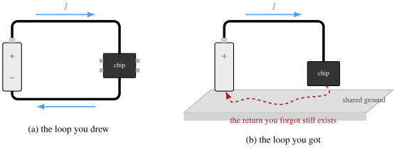
Figure 1: Every current closes a loop. (a) The loop you drew. (b) The loop you got: the forgotten return closes through the shared ground, and everything on that path sees it
When you debug a noisy chip, do not ask “where does this signal go?”. Ask “where does it come back?”. The second question finds the problem.
Don’t ask “where does the signal go?”
Ask “where does it come back?”
The capacitor falls out
Now break the top wire of the loop, as in Figure 2. Kirchhoff panics - the circuit is open. Maxwell does not: charge piles up on the two faces of the break, an electric field grows between them, and the changing field is a current. Ampere’s correction term $\partial D/\partial t$ carries the loop across the gap as if the wire were never cut. Charge conservation is satisfied at every instant; the loop never broke.
A capacitor is a deliberately good gap: two large faces, close together, with a dielectric that multiplies the effect. The $I = C\, dV/dt$ you have used since your first circuits course is Ampere’s displacement current wearing a component symbol.
And because any gap does this, every pair of conductors on your chip is a capacitor whether you asked for one or not - the parasitics chapter is the bill.
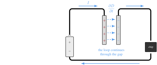
Figure 2: Break the conductor and the loop continues through the gap as displacement current. A capacitor is a deliberately good gap
The inductor falls out
Figure 3(a) walks the three steps. One: push a rising current through a loop of wire, and Ampere says that current wraps a magnetic field around the wire. Two: some of that field threads the loop itself - the flux $\Phi$ is proportional to the current, with a constant decided purely by the geometry, and we call it $L$. Three: Faraday says a changing flux drives a voltage around the loop, and Lenz’s rule says it drives it in the direction that opposes the change. The loop fights you, and at the terminals that reads $v = L\, di/dt$: ramp the current, and the loop answers with a voltage, exactly as the inset shows.
An inductor is a deliberately good loop. Wind the same loop $N$ times, Figure 3(b), and the bargain improves twice over: $N$ turns make $N$ times the flux, and every turn feels all of it - which is why the inductance grows as $N^2$.
The converse of the capacitor’s lesson holds here: every loop on your chip is an inductor whether you asked or not. Since every current runs in a loop, every current has an inductance. That is why fast edges ring - the loop’s $L$ and the gap’s $C$ are always both present, and together they make a resonator you never drew.
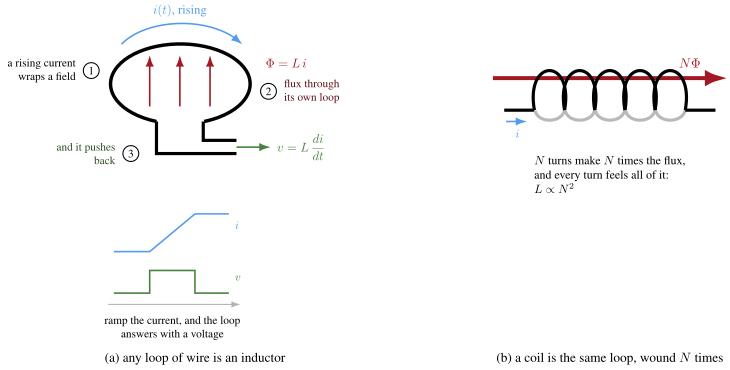
Figure 3: Every loop encloses flux, and a changing current fights its own flux. An inductor is a deliberately good loop; a coil is the same loop N times
Every wire is both
So the fine print reads: every gap is a capacitor, every loop is an inductor, and every current must loop. Put the three together over a ground plane and you can predict something that surprises most people the first time: where the return current flows.
At DC the return current spreads across the whole plane - it minimizes resistance, Figure 4(a). At high frequency it crowds into a narrow band directly under the signal wire, Figure 4(b). It is minimizing impedance, and above a few megahertz the impedance is dominated by the loop inductance - which shrinks with the loop area. The current chooses the smallest loop available.
This one picture is most of signal integrity. Slot the ground plane under a trace and the return detours around the slot: the loop area explodes, the inductance with it. Decoupling works the same way: the capacitor’s value matters less than the loop area between it and the load, because it is the loop inductance that decides how fast the capacitor can deliver charge.
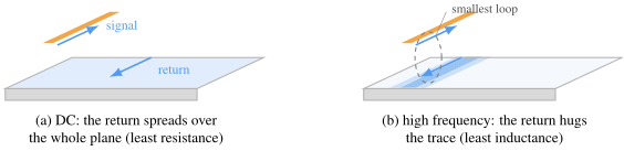
Figure 4: Where the return current flows in a ground plane. (a) At DC it spreads to minimize resistance. (b) At high frequency it hugs the signal wire to minimize loop inductance
The antenna does not radiate
Here is the claim this chapter has been building towards: the metal of an antenna does not radiate. The metal only sets up boundary conditions. The drive sloshes charge up and down the arms; the charge makes fields around the structure; and it is the fields that carry the power away.
Close to the dipole, Figure 5(a), the electric field lines run from one arm to the other. Every half cycle the drive reverses, the field lines collapse back onto the metal, and their energy returns to the circuit. This is the near field: energy borrowed and repaid, which at the terminals looks like reactance - the antenna below resonance is just a capacitor.
But the news that the drive has reversed travels at the speed of light. Field lines further than about $\lambda/2\pi$ from the arms get the news too late: the charge that anchored them has already moved on, and the lines have nothing to end on. Gauss offers them one way out - close on yourself. Figure 5(b): the loops detach, each one a ring of displacement current sustaining the magnetic field of the next (Ampere), which sustains the electric field of the next (Faraday), and the pair leapfrogs outward at $c$ with no metal anywhere. That self-sustaining leapfrog is the electromagnetic wave.
At the antenna terminals, the energy that left with the detached loops never comes back. Power delivered and not returned looks, to the circuit, exactly like a resistor: the radiation resistance. It is the receipt for the escaped loops.
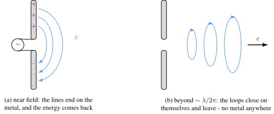
Figure 5: (a) Near the dipole the field lines end on the metal and their energy returns every half cycle. (b) Beyond about lambda over 2 pi the lines close on themselves - displacement current with no metal - and carry power away at c
The wavelength sets the geometry. Figure 6 shows the workhorse as it actually ships: a quarter-wave copper trace on a PCB, fed by the radio chip, over a keep-out where the ground is cut away. The ground pour is the other half of the antenna - the trace’s image in it completes the dipole. The current standing wave is maximum at the feed and zero at the tip, and resonance lands at $l = \lambda/4$: at 2.4 GHz about 31 mm, which is why the antenna region of a Bluetooth board is the size it is, and why nothing on a millimetre scale chip radiates efficiently by accident. Accidental radiators are inefficient antennas - but a receiver channel fighting for -100 dBm does not need your clock harmonic to be efficient, only present.
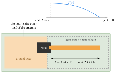
Figure 6: The quarter-wave monopole as it ships, seen from above: the antenna trace on its keep-out, fed by the radio, with the ground pour as the other half of the antenna. Above, on the same scale, the current standing wave that sets l = lambda/4 - about 31 mm at 2.4 GHz
What this buys you on-chip
Everything in this chapter reappears later in the book wearing a different costume.
On-chip inductors are poor because the fine print is against them twice: the loops that fit on a die are small, so $L$ is small, and they sit on a conductive substrate, so Faraday drives eddy-current losses in exactly the silicon we paid so much for. The LC oscillator chapter lives with the resulting Q.
Decoupling capacitors are loop design, not capacitor selection: the inductance of the loop from capacitor to load sets the frequency above which the capacitor stops helping.
Supply and ground bounce are Figure 1(b) at chip scale, and the cure is the same as the diagnosis: give every fast loop a small, deliberate return.
And the radio chapter’s antenna, matching network and Friis budget are this chapter run in reverse: arrange the boundary conditions so the detaching loops are not an accident but the product.
- On-chip inductors: small loops, lossy substrate - the fine print charges twice
- Decoupling is loop design, not capacitor selection
- Ground bounce is Figure 1(b) at chip scale
- A radio is this chapter, run on purpose
Summary
The one-page version of this chapter:
- Circuit theory is Maxwell with the fine print deleted; the fine print still bills you
- Charge conservation means every current closes a loop - the return path is not optional, only its location is
- A capacitor is a deliberately good gap: displacement current carries the loop across
- An inductor is a deliberately good loop: every loop encloses flux, and a changing current fights its own flux
- At high frequency the return current hugs the signal wire, because the smallest loop has the smallest inductance
- The antenna metal only sets boundary conditions: field loops that detach beyond lambda/2pi carry the power, and radiation resistance is their receipt
Would you like to know more?
The best intuition-first treatment of these ideas remains Feynman’s Lectures on Physics, Volume II - chapter 18 for the full set of equations and what they mean, and chapter 24 onward for waveguides and radiation. For the signal-integrity consequences, Howard Johnson’s High-Speed Digital Design (the “black magic” book) is the field manual for Figure 4.
- Feynman Lectures on Physics, Volume II, chapter 18
- Howard Johnson & Martin Graham, High-Speed Digital Design: A Handbook of Black Magic