Fields

1

The four equations, in words

2

\[\oint \vec{E} \cdot d\vec{A} = \frac{Q}{\varepsilon_0}\]

\[\oint \vec{B} \cdot d\vec{A} = 0\]

\[\oint \vec{E} \cdot d\vec{\ell} = -\frac{d\Phi_B}{dt}\]

\[\oint \vec{B} \cdot d\vec{\ell} = \mu_0 I + \mu_0 \varepsilon_0 \frac{d\Phi_E}{dt}\]

Currents always run in loops
3
Don't ask "where does the signal go?"

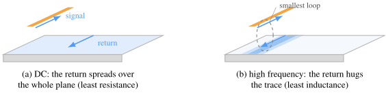
Ask "where does it come back?"

The capacitor falls out

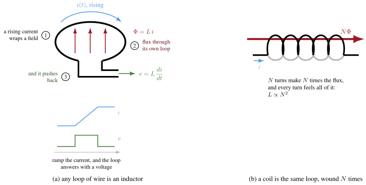
The inductor falls out

Every wire is both

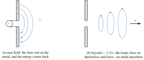
The antenna does not radiate

4

What this buys you on-chip

  • On-chip inductors: small loops, lossy substrate - the fine print charges twice
  • Decoupling is loop design, not capacitor selection
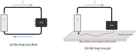
  • Ground bounce is Figure 1(b) at chip scale
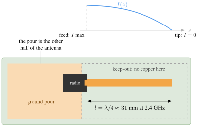
  • A radio is this chapter, run on purpose
5

Summary

  • Circuit theory is Maxwell with the fine print deleted; the fine print still bills you
  • Charge conservation means every current closes a loop - the return path is not optional, only its location is
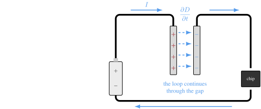
  • A capacitor is a deliberately good gap: displacement current carries the loop across
  • An inductor is a deliberately good loop: every loop encloses flux, and a changing current fights its own flux
  • At high frequency the return current hugs the signal wire, because the smallest loop has the smallest inductance
  • The antenna metal only sets boundary conditions: field loops that detach beyond lambda/2pi carry the power, and radiation resistance is their receipt
6

Would you like to know more?

  • Feynman Lectures on Physics, Volume II, chapter 18
  • Howard Johnson & Martin Graham, High-Speed Digital Design: A Handbook of Black Magic
7