Carsten Wulff 2024
6
The order of execution of events at the same time-step does not matter
The system is causal. Changes in the future do not affect signals in the past or the now
Commercial
Open Source
module dig(
           input wire         clk,
           input wire         reset,
           output logic [4:0] b
           );

   logic                      rst = 0;

   always_ff @(posedge clk) begin
      if(reset)
        rst <= 1;
      else
        rst <= 0;
   end

   always_ff @(posedge clk) begin
      if(rst)
        b <= 0;
      else
        b <= b + 1;
   end // dig

endmodule
parse spice netlist, and setup partial/ordinary differential equations for node matrix
\[\begin{pmatrix} G_{11} &G_{12} &\cdots &G_{1N} \\ G_{21} &G_{22} &\cdots &G_{2N} \\ \vdots &\vdots &\ddots & \vdots\\ G_{N1} &G_{N2} &\cdots &G_{NN} \end{pmatrix} \begin{pmatrix} v_1\\ v_2\\ \vdots\\ v_N \end{pmatrix}= \begin{pmatrix} i_1\\ i_2\\ \vdots\\ i_N \end{pmatrix}\]
model the non-linear current/voltage behavior between all nodes
numerical methods to compute time evolution
SPICE (Simulation Program with Integrated Circuit Emphasis) published in 1973 by Nagel and Pederson
Commercial - Cadence Spectre - Siemens Eldo - Synopsys HSPICE
Free - Aimspice - Analog Devices LTspice - xyce
Open Source - ngspice
Tutorial at http://analogicus.com/jnw_sv_sky130a/
Repository at https://github.com/wulffern/jnw_sv_sky130a
Assumes knowledge of Tutorial
module dig(
           input wire         clk,
           input wire         reset,
           output logic [4:0] b
           );

   logic                      rst = 0;

   always_ff @(posedge clk) begin
      if(reset)
        rst <= 1;
      else
        rst <= 0;
   end

   always_ff @(posedge clk) begin
      if(rst)
        b <= 0;
      else
        b <= b + 1;
   end // dig
endmodule
cd sim/JNWSW_CM
ngspice vlnggen ../../rtl/dig.v
perl ../../tech/script/gensvinst ../../rtl/dig.v dig
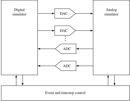
The script generates an svinst.spi file. The first section imports the
digital compiled library
adut [clk
+ reset
+ ]
+ [b.4
+ b.3
+ b.2
+ b.1
+ b.0
+ ] null dut
.model dut d_cosim
+ simulation="../dig.so" delay=10p
* Inputs
Rsvi0 clk 0 1G
Rsvi1 reset 0 1G

* Outputs
Rsvi2 b.4 0 1G
Rsvi3 b.3 0 1G
Rsvi4 b.2 0 1G
Rsvi5 b.1 0 1G
Rsvi6 b.0 0 1G
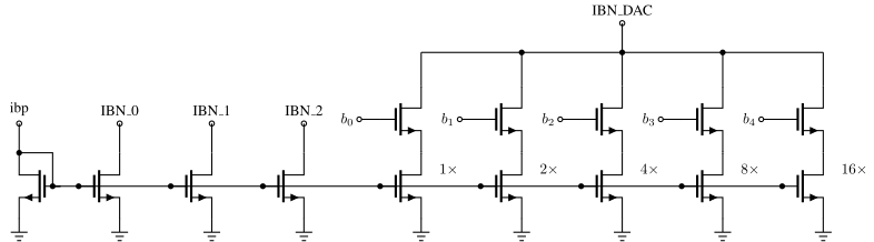
E_STATE_b dec_b 0 value={( 0
+ + 16*v(b.4)/AVDD
+ + 8*v(b.3)/AVDD
+ + 4*v(b.2)/AVDD
+ + 2*v(b.1)/AVDD
+ + 1*v(b.0)/AVDD
+)/1000}
.save v(dec_b)
...

.include ../xdut.spi
.include ../svinst.spi

* Translate names
VB0 b.0 b<0> dc 0
VB1 b.1 b<1> dc 0
VB2 b.2 b<2> dc 0
VB3 b.3 b<3> dc 0
VB4 b.4 b<4> dc 0

...
*- Override the default digital output bridge.
pre_set auto_bridge_d_out =
     + ( ".model auto_dac dac_bridge(out_low = 0.0 out_high = 1.8)"
     +   "auto_bridge%d [ %s ] [ %s ] auto_dac" )
cd sim/JNWSW_CM/
make typical