Overview
Overview
GDS workflow DRC workflow LVS workflow DOCS workflow
Who
Carsten Wulff
Why
Example of a temperature sensor
How
One way to make a temperature sensor is to create a temperature dependent oscillator, and then measure the frequency of the oscillator. In Figure 0 we can see an overview.
A bandgap circuit is used to make a current that is proportional to absolute temperature ($I_{PTAT}$) and a voltage that is complementary to absolute temperature ($V_{CTAT}$). A relaxation oscillator converts the current and voltage into a frequency ($f_{OSC}$). A digital finite-state-machine and a counter converts the frequency to a digital value that is proportional to temperature.
[Image: SVG not converted]
Figure 0: System overview
This temperature sensor was made to conform to the specification at The Project: Design a temperature sensor.
For more information on the oscillator, see Schematics.
To measure the frequency of the oscillator we need a frequency reference. One reference that is usually available in a MCU system is a 32768 Hz oscillator ($f_{32KI}$ in Figure 0). The reason for that specific frequency is to accurately be able to count to 1 second with a binary counter, and apparently to have a frequency for the crystal that is higher than 20 kHz, so we can’t hear it (according to https://youtu.be/_2By2ane2I4?si=8ltUNqAPL71zCQUW).
The principle of operation of the FSM and counter can be seen in Figure 1.
The FSM starts in a IDLE state where a counter is reset. Next the temperature dependent oscillator is started, and a number of oscillator pulses are counted. The FSM runs on LF_CLK and we use the count x LF_CLK to measure the oscillation frequency.
After one clock period the FSM powers down the oscillator. In the CAPTURE state the value of the counter is stored, and the FSM returns to idle.
[Image: SVG not converted]
Figure 1: Finite-State Machine to control temperature sensor
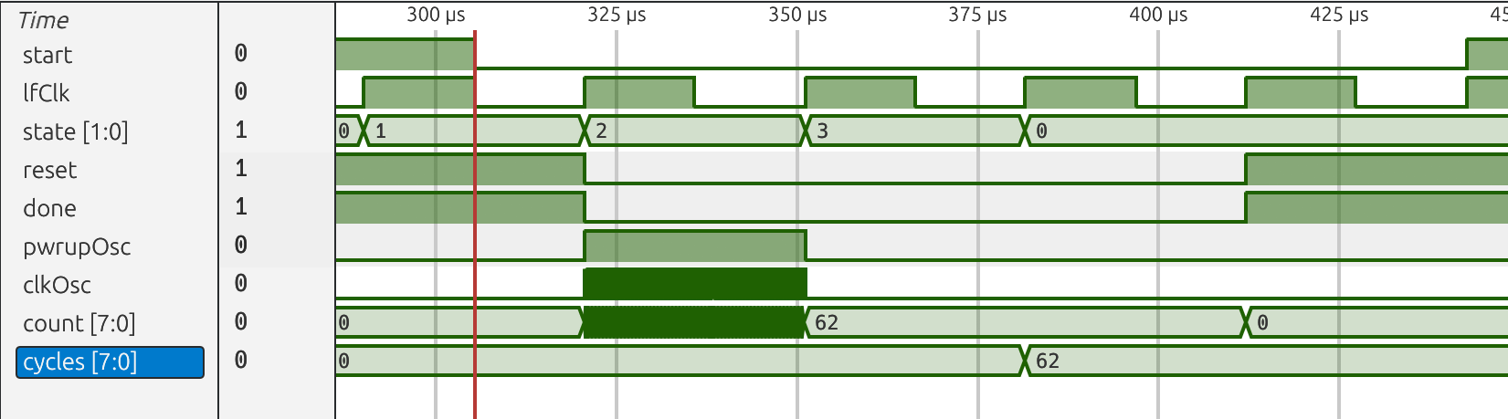
A waveform of the sequence can be seen in Figure 2. When the signal start is asserted the FSM transitions to power up the oscillator (pwrupOsc=1), and we can notice the clkOsc counts the clock pulses of the oscillator. On the next lfClk the oscillator is shut down and the counter naturally stops. The value from the oscillator is stored in the cycles register.
Figure 2: Waves from simulation of the oscillator
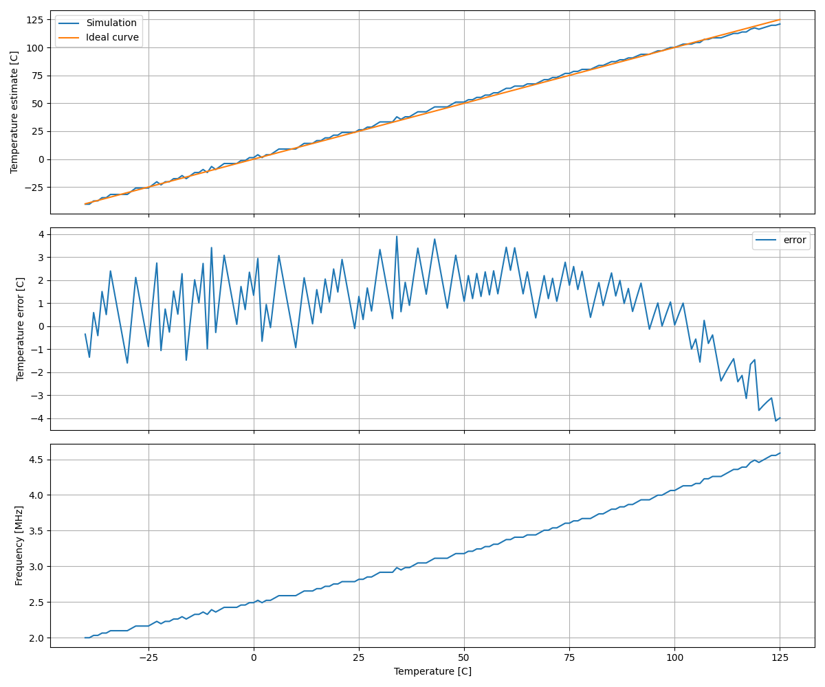
In the testbench I store the cycles, and the testbench temperature to a file, and use tb.py to plot the transfer function.
I use a physical model of the oscillator (LELO_TEMP.py) to create a function to turn the frequency back to a temperature. It can be seen that the frequency has a non-zero second order derivative, and thus, the shape of the curve needs to be compensated for. See the python model for details.
Figure 3: Simulation of the verilog model of the oscillator
Layout direction
The layout flow in this repository is currently moving from plain schematic-to-layout generation toward a more analog-aware compiler flow.
The goal is to get an agent to write the necessary python to do the layout.
This work is described in more detail in LAYOUT_FLOW.md.
What
| What | Cell/Name |
|---|---|
| Schematic | design/LELO_TEMP_SKY130A/LELO_TEMP.sch |
| Layout | design/LELO_TEMP_SKY130A/LELO_TEMP.mag |
| Verilog Model | design/LELO_TEMP_SKY130A/LELO_TEMP.v |
| Verilog Counter | rtl/tempCounter.v |
| Verilog Fsm | rtl/tempFsm.v |
| Verilog TB | sim/tb_lelo_temp/tb.v |
| Analog top TB | sim/LELO_TEMP/tran.spi |
Signal interface
| Signal | Direction | Domain | Description |
|---|---|---|---|
| VDD_1V8 | Input | VDD_1V8 | Main supply |
| PWRUP_1V8 | Input | VDD_1V8 | Power up the temperature dependent oscillator |
| OSC_TEMP_1V8 | Output | VDD_1V8 | Temperature dependent frequency |
| VSS | Input | Ground |
Key parameters
| Parameter | Min | Typ | Max | Unit |
|---|---|---|---|---|
| Technology | Skywater 130 nm | |||
| AVDD | 1.7 | 1.8 | 1.9 | V |
| Oscillation frequency | 1.7 | 3.0 | 4.0 | MHz |
| Temperature | -40 | 27 | 125 | C |
Simulation graphs
Typical temperature error of the sensor is low, but I’ve calibrated the second order correction for typical conditions.
Over mismatch and extreme test condition (ETC) the temperature error increase.
Figure 4: Typical simulation results of the oscillator
Figure 5: Mismatch simulation of the oscillator
Figure 6: Extreme test conditions (PVT) simulation of oscillator
Install
Clone LELO_TEMP_SKY130A
To install, do the following
python3 -m pip install cicconf
git clone --recursive https://github.com/wulffern/lelo_temp_sky130a lelo_temp_sky130a
cicconf --rundir ./ --config lelo_temp_sky130a/config.yaml clone --https
Schematics
LELO_TEMP_SKY130A
LELOTEMP_BIAS_IBP
Bandgap core. The voltage across the resistor between VR1 and VD2 will be
\[\Delta V = V_{R1} - V_{D2} = \frac{k T}{q} ln(8 \times 8)\]since there is a 1-to-8 ratio between the bipolars, and a 1-to-8 ratio in the current mirror.
The current in the resistor will be
\[I_{R} = \frac{\Delta V}{(4 + 8) \times RPPO}\]Where $RPPO$ is the unit resistor.
The $V_C$ is a bit more complicated, but can be calculated to be
\[V_C = \frac{kT}{q}(\ell - 3 \ln T) + V_G\]where
\[\ell= \ln{I_D} - \ln{\left (Aq\frac{D_n}{L_n N_A} + \frac{D_p}{L_p N_D}\right)} - 2 \ln{\sqrt{B_c B_v}}\]where $A$ is the area of the diode, $I_D$ the current in the diode, $D_n,D_p$ are the diffusion constants for electrons and holes. $L_n,L_p$ are the diffusion lengths, $N_A,N_D$ are the acceptor and donor concentration. and $B_c,B_v$ are
\[B_c = 2 \left[\frac{2 \pi k m_n^*}{h^2}\right]^{3/2} \text{ } B_v = 2 \left[\frac{2 \pi k m_p^*}{h^2}\right]^{3/2}\]where $m_n,m_p$ are the effective mass of electrons and holes and $h$ is Planck’s constant.
Obviously.
Not really.
But it is understandable.
See Diodes
Estimated values from the model in LELO_TEMP.py are shown in table below.
| Temperature [C] | Current [uA] | Vc [V] | DeltaV [mV] |
|---|---|---|---|
| -40 | 0.902 | 0.8386 | 83.6 |
| 25 | 1.133 | 0.7412 | 106.9 |
| 125 | 1.470 | 0.5844 | 142.7 |
The table was generated from model.ipynb
The diode connected transistor on the right side is to clamp the voltage between VR1 and VD2. If the current is too high, then a high voltage on VR1 can turn off the PMOS in the OTA, and increase settling time.
[Image: SVG not converted]
LELOTEMP_OTAN
Current mirror OTA. The bias is provided by the resistor from the tail of the differential pair to VSS. With the CTAT voltage at the input the current should remain stable. I’m not using the bias current from the bandgap because I don’t want to complicate the loop startup behavior.
The output of the OTA is pull high in power down to ensure that the PMOS current mirror in the bandgap is turned off in power down.
The circuit on the right side is used to generate the cascode bias for the main bandgap.
The circuit on the far right is the startup circuit. The current from the bandgap is fed to a very long PMOS. The VSTART1 voltage is buffered, and used to pull down the VCP and VO voltage to get the loop started. If there is no current flowing, then VSTART1 will be high. If there is some current then VSTART1 will be low.
[Image: SVG not converted]
LELO_TEMP
Bandgap (LEOTEMP_BIAS_IPB) is used to provide a PTAT current for the frequency conversion and the comparator. The $V_C$ is the CTAT diode voltage in the bandgap. The output current is approximately 1 uA.
The current charges the capacitor inside CCMP. When the voltage on the capacitor reaches $V_C$ the comparator inside CCMP will trigger (low to high).
The two comparators alternate to trigger the set/reset latch made by the NOR gates. As such, the two capacitors are alternatively charged.
The output frequency can be calculated from the voltage/current relationship of a capacitor.
A single charge cycle is given by
\[I = C \frac{dV}{dt} \Rightarrow dt = C \frac{V_C}{I}\]Inserting for the bandgap current ($I_R$)
\[dt = RC \frac{V_C}{\Delta V}\]As such, the frequency will be
\[f_{OSC} = \frac{1}{2 dt} = \frac{1}{2RC} \frac{\Delta V}{V_C}\]The $\Delta V$ increases with temperature and $V_C$ decreases with temperature, turns out the $\Delta V$ increases faster than $V_C$ drops, so the overall gradient is positive.
The estimated frequency is shown in the table below (the table was generated from model.ipynb))
| Temperature [C] | Frequency [MHz] |
|---|---|
| -40 | 1.858 |
| 25 | 2.634 |
| 125 | 4.310 |
[Image: SVG not converted]
LELOTEMP_CCMP
[Image: SVG not converted]
LELOTEMP_CMP
A two-stage OTA used as comparator. Uses a 1U bias current from the bandgap
[Image: SVG not converted]
TB_LELO_TEMP
A top level debug testbench for the temperature sensor. If you open the testbench in Xschem you’ll see there are waveforms to view signals inside the temperature sensor.
A debug testbench like this is quite useful to figure out what’s going on, and see what voltages and currents are present in the design.
[Image: SVG not converted]
Simulations
- TOC
LELO_TEMP_SKY130A
LELOTEMP_BIAS_IBP
README.md: “47cfd66 Sun May 3 22:41:03 2026 +0200 “
Loop stability (lstb)
Check stability
| Name | Parameter | Description | Min | Typ | Max | Unit | |
|---|---|---|---|---|---|---|---|
| Gain Margin | gm_db | Spec | -50.00 | -10.00 | -10.00 | dB | |
| Sch_typ | -15.24 | ||||||
| Sch_etc | -31.04 | -16.50 | -12.85 | ||||
| Sch_3std | -18.71 | -15.65 | -12.60 | ||||
| DC gain | lf_gain | Spec | 50.00 | 40.00 | 80.00 | dB | |
| Sch_typ | 69.07 | ||||||
| Sch_etc | 65.77 | 67.28 | 69.86 | ||||
| Sch_3std | 66.68 | 68.81 | 70.95 | ||||
| Phase Margin | pm_deg | Spec | 45.00 | 60.00 | 90.00 | ||
| Sch_typ | 58.63 | ||||||
| Sch_etc | 48.41 | 62.56 | 70.99 | ||||
| Sch_3std | 50.86 | 59.70 | 68.53 | ||||
| Unity Gain Frequency | ug | Spec | 3.00 | 15.00 | 100.00 | MHz | |
| Sch_typ | 5.76 | ||||||
| Sch_etc | 2.59 | 5.36 | 10.12 | ||||
| Sch_3std | 3.65 | 5.65 | 7.65 | ||||
| PMOS gate | v(lpo) | Spec | 0.45 | 0.70 | 1.10 | V | |
| Sch_typ | 0.76 | ||||||
| Sch_etc | 0.52 | 0.77 | 1.05 | ||||
| Sch_3std | 0.73 | 0.76 | 0.78 | ||||
| Delta diode voltage | vd | Spec | 80.00 | 106.00 | 150.00 | mV | |
| Sch_typ | 109.25 | ||||||
| Sch_etc | 81.57 | 115.01 | 145.76 | ||||
| Sch_3std | 104.82 | 108.95 | 113.09 | ||||
| Output current | i(v1) | Spec | 0.50 | 1.00 | 2.00 | uA | |
| Sch_typ | 1.08 | ||||||
| Sch_etc | 0.87 | 1.26 | 1.74 | ||||
| Sch_3std | 0.75 | 1.12 | 1.50 | ||||
| VD Error | vdiff | Spec | -6.00 | 0.00 | 6.00 | mV | |
| Sch_typ | -0.08 | ||||||
| Sch_etc | -97.25 | -0.13 | 0.06 | ||||
| Sch_3std | -22.99 | 0.99 | 24.96 |
Transient (tran)
Check settling time and current variation
| Name | Parameter | Description | Min | Typ | Max | Unit | |
|---|---|---|---|---|---|---|---|
| t_settle | Spec | 0.01 | 0.05 | 2.00 | us | ||
| Sch_typ | 0.37 | ||||||
| Sch_etc | 0.31 | 0.40 | 8.84 | ||||
| Sch_3std | 0.35 | 0.37 | 0.40 | ||||
| i0 | Spec | 0.500 | 1.000 | 2.000 | uA | ||
| Sch_typ | 1.160 | ||||||
| Sch_etc | 0.692 | 1.169 | 1.667 | ||||
| Sch_3std | 0.720 | 1.115 | 1.511 | ||||
| i1 | Spec | 0.500 | 1.000 | 2.000 | uA | ||
| Sch_typ | 1.160 | ||||||
| Sch_etc | 0.692 | 1.169 | 1.666 | ||||
| Sch_3std | 0.690 | 1.143 | 1.596 | ||||
| i2 | Spec | 0.500 | 1.000 | 2.000 | uA | ||
| Sch_typ | 1.159 | ||||||
| Sch_etc | 0.692 | 1.168 | 1.666 | ||||
| Sch_3std | 0.720 | 1.122 | 1.525 | ||||
| i3 | Spec | 0.500 | 1.000 | 2.000 | uA | ||
| Sch_typ | 1.159 | ||||||
| Sch_etc | 0.692 | 1.167 | 1.665 | ||||
| Sch_3std | 0.725 | 1.114 | 1.502 | ||||
| idd | Spec | 5.000 | 30.000 | 60.000 | uA | ||
| Sch_typ | 42.766 | ||||||
| Sch_etc | 33.372 | 40.889 | 53.123 | ||||
| Sch_3std | 34.902 | 41.982 | 49.062 |
DC (dc)
Check temperature performance
| Name | Parameter | Description | Min | Typ | Max | Unit | |
|---|---|---|---|---|---|---|---|
| ibp_err_max | Spec | -30.00 | 0.00 | 20.00 | nA | ||
| Sch_typ | 8.38 | ||||||
| Sch_etc | 7.45 | 8.39 | 496.21 | ||||
| Sch_3std | -247.30 | 24.70 | 296.71 | ||||
| ibp_err_min | Spec | -30.00 | 0.00 | 20.00 | nA | ||
| Sch_typ | -18.43 | ||||||
| Sch_etc | -62.25 | -18.47 | -16.39 | ||||
| Sch_3std | -53.14 | -19.39 | 14.35 | ||||
| imax | Spec | 0.50 | 0.00 | 2.00 | uA | ||
| Sch_typ | 1.46 | ||||||
| Sch_etc | 1.29 | 1.46 | 1.67 | ||||
| Sch_3std | 1.00 | 1.41 | 1.82 | ||||
| imin | Spec | 0.50 | 0.00 | 2.00 | uA | ||
| Sch_typ | 0.92 | ||||||
| Sch_etc | 0.81 | 0.91 | 1.05 | ||||
| Sch_3std | 0.49 | 0.87 | 1.25 | ||||
| a_per_c | Spec | 1.00 | 3.00 | 5.00 | nA | ||
| Sch_typ | 3.27 | ||||||
| Sch_etc | 2.90 | 3.27 | 3.75 | ||||
| Sch_3std | 2.74 | 3.25 | 3.76 |
LELOTEMP_OTAN
LELO_TEMP
README.md: “47cfd66 Sun May 3 22:41:03 2026 +0200 “
LELO_TEMP
Temperature sensor (tran)
Check temperature accuracy
| Name | Parameter | Description | Min | Typ | Max | Unit | |
|---|---|---|---|---|---|---|---|
| idd_25 | Spec | 5.000 | 30.000 | 100.000 | uA | ||
| Sch_typ | 79.330 | ||||||
| Sch_etc | 57.444 | 78.728 | 103.453 | ||||
| Sch_3std | 70.694 | 81.108 | 91.521 | ||||
| iddq_25 | Spec | 0.000 | 10.000 | 50.000 | nA | ||
| Sch_typ | 5.229 | ||||||
| Sch_etc | 4.285 | 5.328 | 44.888 | ||||
| Sch_3std | 5.067 | 5.280 | 5.493 | ||||
| ind_1p_max | Industrial 1 point calibration | Spec | -15.000 | 0.000 | 15.000 | C | |
| Sch_typ | 11.916 | ||||||
| Sch_etc | 2.570 | 8.559 | 21.027 | ||||
| Sch_3std | 0.221 | 10.293 | 20.364 | ||||
| ind_1p_min | Industrial 1 point calibration | Spec | -15.000 | 0.000 | 15.000 | C | |
| Sch_typ | -5.970 | ||||||
| Sch_etc | -68.775 | -8.264 | 0.612 | ||||
| Sch_3std | -12.166 | -6.474 | -0.782 | ||||
| ind_2p_max | Industrial 2 point calibration | Spec | -10.000 | 0.000 | 10.000 | C | |
| Sch_typ | 1.882 | ||||||
| Sch_etc | -0.570 | 3.580 | 13.200 | ||||
| Sch_3std | -1.293 | 1.480 | 4.254 | ||||
| ind_2p_min | Industrial 2 point calibration | Spec | -10.000 | 0.000 | 10.000 | C | |
| Sch_typ | -0.872 | ||||||
| Sch_etc | -57.140 | -3.769 | 1.481 | ||||
| Sch_3std | -3.701 | -1.281 | 1.139 | ||||
| com_1p_max | Commercial 1 point calibration | Spec | -10.000 | 0.000 | 10.000 | C | |
| Sch_typ | 3.684 | ||||||
| Sch_etc | -0.294 | 4.651 | 11.925 | ||||
| Sch_3std | -0.376 | 3.506 | 7.387 | ||||
| com_1p_min | Commercial 1 point calibration | Spec | -10.000 | 0.000 | 10.000 | C | |
| Sch_typ | -2.400 | ||||||
| Sch_etc | -10.763 | -2.672 | 0.612 | ||||
| Sch_3std | -4.426 | -2.340 | -0.254 | ||||
| com_2p_max | Commercial 2 point calibration | Spec | -5.000 | 0.000 | 5.000 | C | |
| Sch_typ | 0.056 | ||||||
| Sch_etc | -0.570 | 0.901 | 5.237 | ||||
| Sch_3std | -0.487 | 0.344 | 1.175 | ||||
| com_2p_min | Commercial 2 point calibration | Spec | -5.000 | 0.000 | 5.000 | C | |
| Sch_typ | -0.872 | ||||||
| Sch_etc | -7.653 | -1.036 | 1.481 | ||||
| Sch_3std | -1.195 | -0.707 | -0.219 | ||||
| FOM | Figure Of Merit | Spec | 10.000 | 40.000 | 400.000 | nAK | |
| Sch_typ | 27.316 | ||||||
| Sch_etc | 27.675 | 83.512 | 247.144 | ||||
| Sch_3std | -1.208 | 31.393 | 63.994 |