l6_project
- TFE4152 - Lecture 6
- Project
- Goal for today
- Goal
- A 10 000 Frames/s CMOS Digital Pixel Sensor
- SENSOR
- COMP
- MEMORY
- Minimum implementation
- Things it’s OK to ignore
- Gray codes
- Analog Simulators
- Digital Simulators
- Mixed-Signal Simulators
- What you get
- Model of 2 x 2 pixel array in SystemVerilog
- State machine
- Top verilog
- SPICE of pixel sensor
- Report 1/2
- Report 2/2
- Proposed plan
- What you get
TFE4152 - Lecture 6
Project
Source
Goal for today
Make it easier to understand the project
Project
- 30 % of final grade
- Groups of 2 people. Find a partner soon. Sign up on blackboard.
- Deadline: 19’th November before 12:00 (24 hour format).
- Strict deadline, \(t > 12:00 \equiv fail\). Both members in group must submit report.
Goal
Be inspired by the ISSCC paper, and design a similar system.
Design analog circuits in SPICE
Design digital circuits in SystemVerilog
A 10 000 Frames/s CMOS Digital Pixel Sensor
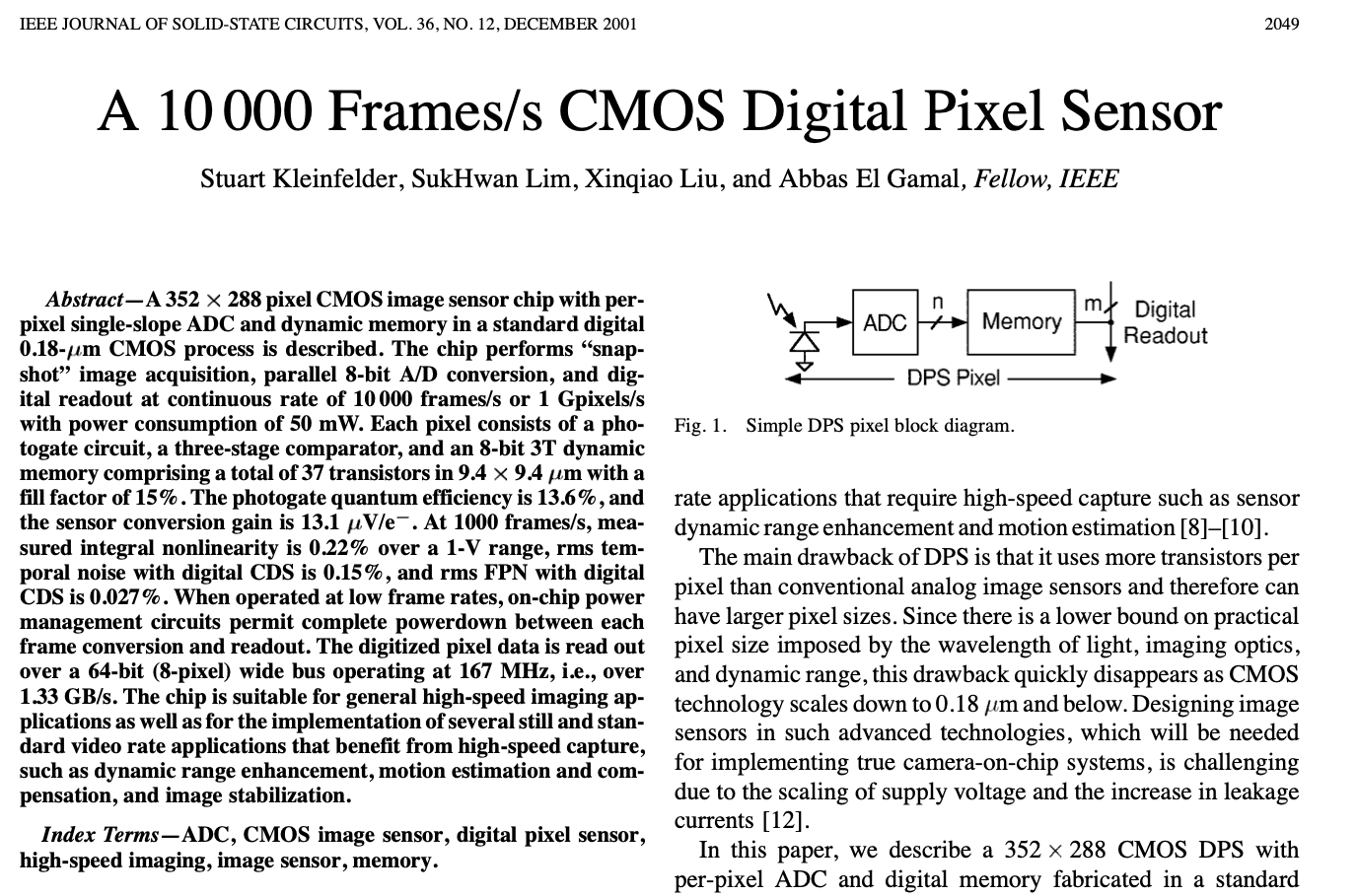
image ../ip/idea.png removed photon sensor \(\Rightarrow\) local analog to digital converter \(\Rightarrow\) local memory
image ../ip/concept.png removed
image ../ip/block_diagram.pdf removed
image ../ip/block_diagram_modified.pdf removed
image ../ip/pixelSensor.png removed
image ../ip/sensor.png removed
SENSOR

COMP
image ../ip/comparator.png removed
image ../ip/memory.png removed
MEMORY
image ../ip/options.png removed
image ../ip/timing_diagram.png removed
Minimum implementation
- Model of 2 x 2 pixel array in SystemVerilog
- State machine to control reset, exposure, analog-to-digital conversion, and readout of the pixel array
- SPICE of pixel sensor (sensor, comparator)
- Report documenting that the circuits (analog and digital) work as designed
Things it’s OK to ignore
- Transistor corners
- Gray counter (but if you do, then it will be hard to get the ADC accurate)
- Voltage variation
- Temperature variation
- “nice to have features”, like power optimalization, testability
Gray codes
| Decimal | Binary | Gray |
|---|---|---|
| 0 | 000 | 000 |
| 1 | 001 | 001 |
| 2 | 010 | 011 |
| 3 | 011 | 010 |
| 4 | 100 | 110 |
| 5 | 101 | 111 |
| 6 | 110 | 101 |
| 7 | 111 | 100 |
dicex/sim/verilog/graycounter.v
module graycounter(out, clk, reset);

   parameter WIDTH = 8;

   output [WIDTH-1 : 0] out;
   input                clk, reset;

   logic [WIDTH-1 : 0]  out;
   wire                 clk, reset;

   logic [WIDTH-1 : 0]  q;


   always @(posedge clk or posedge reset) begin
      if (reset)
        q <= 0;
      else begin
         q <= q + 1;
      end
      out <= {q[WIDTH-1], q[WIDTH-1:1] ^ q[WIDTH-2:0]};
   end

endmodule // graycounter


Analog Simulators
aimspice, ngspice, spectre, eldo, hspice
Time evolution (transient analysis) is a numerical analysis to differential equations for voltage and current. For example Newton’s method
- Take a small time step, iterate numerical analysis until error is low enough, if error is too large, chose shorter time step
- Go to 1
For more info, see In a Nutshell: How SPICE Works
Can simulate digital circuits, but very slowly
Digital Simulators
iverilog, questa, xcelium, vcs
Time evolution with time steps, and delta-time
- Next time step (i.e clock cycle)
- What signals change at this time step?
- Compute new signal values, and schedule changes in future
- Should any of the signals that changed now affect other signals now? If yes, then take delta time step
- If delta timestep, then go to 2. If no more delta timestep, go to 1.
Cannot simulate analog differential equations!
Mixed-Signal Simulators
Control time in both analog and digital simulator
Provide analog-to-digital and digital-to-analog converters to “mirror” signals in the other simulator
Not sure there is an open source mixed-signal simulator

What you get
project/
├── spice/
│   ├── Makefile                # See https://www.gnu.org/software/make/manual/html_node/Introduction.html
│   ├── pixelSensor.cir         # Almost empty circuit for pixelSensor
│   └── pixelSensor_tb.cir      # SPICE testbench for pixelSensor, emulates verilog
└── verilog/
    ├── Makefile
    ├── pixelSensor.fl          # Verilog file list
    ├── pixelSensor_tb.gtkw     # Save file for GTKWave
    ├── pixelSensor_tb.v        # Verilog testbench for pixelSensor
    └── pixelSensor.v           # Verilog model of analog pixelSensor circuit
What you should do
Model of 2 x 2 pixel array in SystemVerilog
Make a SystemVerilg module (i.e pixelArray.v), that use pixelSensor.v
Figure out which signals need to be a bus, and what signals are common for the pixels
Make a testbench pixelArray_tb.v to check that the pixelArray.v compiles and do some rudementary tests to check that you’ve hooked things up correctly
State machine
Make a SystemVerilog module pixelState.v that can connect to pixelArray.v
Make a state machine to control reset, exposure, analog-to-digital conversion, and readout of the pixel array
Make a testbench pixelState_tb.v to test the state machine
Top verilog
Make a SystemVerilog module pixelTop.v that connects pixelState.v to pixelArray.v
Make a testbench pixelTop_tb.v to test the statemachine and readout of the 2 x 2 array
SPICE of pixel sensor
Copy pixelSensor.cir to another name
Copy pixelSensor_tb.cir to another name
Make the design from the paper (Fig. 4)
- Sensor (SENSOR)
- Comparator (COMP)
- Memory (MEMORY)
Add something (like Rphoto in pixelSensor.tb) to model the photocurrent.
Add a testbench for each subcircuit (COMP, SENSOR, MEMCELL, MEMORY)
Report 1/2
- Introduction = Why?
- Theory = How?
- As little information as possible. Give references to sources. Assume that the reader has read the paper.
- Implementation = What?
- Describe what you designed
- State diagrams, with explanation
- Circuit diagrams, with explanation
- One sub-chapter per block
Report 2/2
- Verification = Are you sure it works?
- Describe your testbenches, and how you verified your design
- Describe key results
- Describe known problems (incase something does not work)
- Discussion and conclusion = Why do you deserve a good grade?
- Appendix
- SPICE netlist
- SystemVerilog netlists
- SystemVerilog testbenches
Proposed plan
| Week | Plan |
|---|---|
| 34 | Register group |
| 35 | Read and understand paper |
| 36 | Sketch what you want to do |
| 37 | Write theory chapter in report |
| 38 | Design & simulation |
| 39 | Design & simulation |
| 40 | Design & simulation |
| 41 | Design & simulation |
| 42 | Verification |
| 43 | Verification |
| 44 | Write report |
| 45 | Write report |
| 46 | Deadline |
What you get
project/
├── spice/
│   ├── Makefile                # See https://www.gnu.org/software/make/manual/html_node/Introduction.html
│   ├── pixelSensor.cir         # Almost empty circuit for pixelSensor
│   └── pixelSensor_tb.cir      # SPICE testbench for pixelSensor, emulates verilog
└── verilog/
    ├── Makefile
    ├── pixelSensor.fl          # Verilog file list
    ├── pixelSensor_tb.gtkw     # Save file for GTKWave
    ├── pixelSensor_tb.v        # Verilog testbench for pixelSensor
    └── pixelSensor.v           # Verilog model of analog pixelSensor circuit
Let’s check what’s inside the files