l6_model_passive
- TFE4152 - Lecture 6
- Models and passives
- Maze status (Exercise 6)
- Goal for today
- p-, p, p+, n-, n, n+
- Metal in ICs is not wire in schematic
- Polysilicon
- Diffusion
- Metal
- What is S, M, L, XL on a chip?
- Metal-Oxide-Metal finger capacitors
- MOS capacitors
- Variation in passives
- Relative precision
- Diodes
- Electrostatic Discharge
TFE4152 - Lecture 6
Models and passives
Source
| Week | Book | Monday | Book | Friday |
|---|---|---|---|---|
| 34 | Introduction, what are we going to do in this course. Why do you need it? | WH 1 , WH 15 | Manufacturing of integrated circuits | |
| 35 | CJM 1.1 | pn Junctions | CJM 1.2 WH 1.3, 2.1-2.4 | Mosfet transistors |
| 36 | CJM 1.2 WH 1.3, 2.1-2.4 | Mosfet transistors | CJM 1.3 - 1.6 | Modeling and passive devices |
| 37 | Guest Lecture - Sony | CJM 3.1, 3.5, 3.6 | Current mirrors | |
| 38 | CJM 3.2, 3.3,3.4 3.7 | Amplifiers | CJM, CJM 2 WH 1.5 | SPICE simulation and layout |
| 39 | Verilog | Verilog | ||
| 40 | WH 1.4 WH 2.5 | CMOS Logic | WH 3 | Speed |
| 41 | WH 4 | Power | WH 5 | Wires |
| 42 | WH 6 | Scaling Reliability and Variability | WH 8 | Gates |
| 43 | WH 9 | Sequencing | WH 10 | Datapaths - Adders |
| 44 | WH 10 | Datapaths - Multipliers, Counters | WH 11 | Memories |
| 45 | WH 12 | Packaging | WH 14 | Test |
| 46 | Guest lecture - Nordic Semiconductor | |||
| 47 | CJM | Recap of CJM | WH | Recap of WH |
Maze status (Exercise 6)
| User | Clock Cycles |
|---|---|
| martinmm | 240 |
| carstenw | 3471 |
Goal for today
- Common questions
- Metal
- Resistors
- Capacitors
- Inductors
- Diodes
- Electrostatic discharge
p-, p, p+, n-, n, n+
What does p-, p, p+ mean? We usually dope with \(N_A \approx 10^{21}\) to \(N_A \approx 10^{25}\) per \(m^3\)
\[N_{A(p-)} < N_{A(p)} < N_{A(p+)}\]Why use it? Imagine a \(n+\) region in a \(p-\) material. We then know that \(N_A << N_D\) and the depletion region is mostly on the \(p-\) side.
How does \(n_i\) change with temperature?
Roughly doubles every 11 degrees (simple model)
\(n_i \approx 1.1e10 \times 2^{\frac{T - 300.15}{11}}\) [\(1/cm^3\)]
BSIM 4.8, Intrinsic carrier concentration (page 122)
\[n_i = 1.45e10\frac{TNOM}{300.15}\sqrt{\frac{T}{300.15}}exp\left[21.5565981 - \frac{qE_g(TNOM)}{2 k_b T}\right]\]from scipy import constants
import numpy as np
import matplotlib.pyplot as plt
k_b = constants.Boltzmann
q = constants.physical_constants["elementary charge"][0]
E_g = 1.13
TNOM = 300.15
T = np.arange(TNOM,TNOM + 100)
n_i_simple = 1.1e10 * 2**((T - TNOM)/11)
n_i_bsim = 1.45e10*(TNOM/300.15) * np.sqrt(T/300.15) \
* np.exp(21.5565981 - (q*E_g)/(2*k_b*T))
plt.semilogy(T,n_i_simple,label="Simple")
plt.semilogy(T,n_i_bsim,label="BSIM 4.8")
plt.legend()
plt.xlabel("Temperature [K]")
plt.ylabel(" $n_i$ [$1/cm^3$]")
plt.savefig("l6_ni.pdf")
plt.show()

Passives
Metal in ICs is not wire in schematic
Resistance ~ m\(\Omega\)/\(\square\)
Capacitance ~ aF/\(\mu\)m to fF/\(\mu\)m
Inductance ~ nH/mm
Max current ~ mA/\(\square\)

| Layout | Must simulate/know |
|---|---|
| All | C Imax |
| Analog, Power | R C Imax |
| Some RF, Some Power | R L C Imax |
Layout parasitic extraction Calibre xRC Synopsys StarRC Cadence Quantus
3D EM Simulators Keysight ADS HFSS
Transistor CAD (TCAD) Synopsys TCAD
Resistors
Polysilicon
Often two types, with, and without silicide
Silicide reduces resistance of polysilicon

Diffusion
Use doped region as resistor
Usually without silicide
Non-linear capacitance
Tricky temperature dependence

Metal
Usually too low omhic to be a useful resistor
Useful for “separating nets” in schematic and layout
Must be considered for power supply and ground routing (high currents)

Capacitors
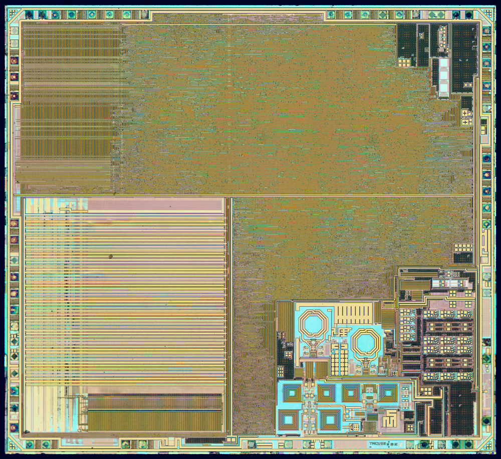
What is S, M, L, XL on a chip?
nRF52832 \(3200 \mu m \times 3000 \mu m = 9600 k \mu m^2\)
S \(< 5 \text{ } k\mu m^2\) M \(< 50 \text{ } k\mu m^2\) L \(< 200 \text{ } k\mu m^2\) XL \(> 200 \text{ } k\mu m^2\)

Metal-Oxide-Metal finger capacitors
Unit capacitance \(\approx 1 fF/\mu m^2/layer\)
\[10 pF = 100 \mu m \times 100 \mu m = 10 k \mu m^2\]
MOS capacitors

dicex/sim/spice/NCHIO/vcap.cir
* gate cap

.include ../../../models/ptm_130.spi

vdrain D 0 dc 1
vgaini G 0 dc 0.5
vbulk B 0 dc 0
vcur S 0 dc 0

M1 D G S B nmos  w=1u  l=1u

.op
Moscap \(\approx 10 fF / \mu m^2\)
\[10 pF = 31 \mu m \times 31 \mu m \approx 1 k \mu m^2\]dicex/sim/spice/NCHIO/vcap.vlog
Device m1:
	Vgs     (gate-source voltage)        [V] : 0.5
	Vgd     (gate-drain voltage)         [V] : -0.5
	Vds     (drain-source voltage)       [V] : 1
	Vbs     (bulk-source voltage)        [V] : 1.90808e-12
	Vbd     (bulk-drain voltage)         [V] : -1
	Id      (drain current)              [A] : 7.32634e-06
	Is      (source current)             [A] : -7.32633e-06
	Ibd     (bulk-drain current)         [A] : -1.01e-12
	Ibs     (bulk-source current)        [A] : 9.581e-25
	Vt      (threshold voltage)          [V] : 0.378198
	Vgt     (gate overdrive voltage)     [V] : 0.121802
	Vgsteff (effective vgt)              [V] : 0.12515
	Gm      (transconductance)           [S] : 8.44164e-05
	Gmb     (bulk bias transconductance) [S] : 2.00071e-05
	Ueff    (mobility)             [cm^2/Vs] : 417.675
	Gds     (channel conductance)        [S] : 1.95043e-07
	Rds     (output resistance)        [Ohm] : 5.12708e+06
	Vdsat   (drain saturation voltage)   [V] : 0.14171
	IC      (inversion coefficient)       [] : 4.42478
	Cgs     (gate-source capacitance)    [F] : 9.98457e-15
	Csg     (source-gate capacitance)    [F] : 5.86932e-15
	Cgd     (gate-drain capacitance)     [F] : 3.98239e-16
	Cdg     (drain-gate capacitance)     [F] : 3.91086e-15
	Cds     (drain-source capacitance)   [F] : 4.30968e-15
	Cgg     (gate-gate capacitance)      [F] : 1.05198e-14
	Cdd     (drain-drain capacitance)    [F] : 1.05198e-14
	Css     (source-source capacitance)  [F] : 0
	Cgb     (gate-bulk capacitance)      [F] : 1.05198e-14
	Cbg     (bulk-gate capacitance)      [F] : 1.74123e-15
	Cbs     (bulk-source capacitance)    [F] : 8e-16
	Cbd     (bulk-drain capacitance)     [F] : 3.97768e-16
Varactors (voltage dependent capacitor)

Inductors
Usually two top metals, because they are thick (low ohmic)
Use foundry model
3D electro magnetic simulation often needed
Variation in passives
Absolute value for resistors and capacitors $\approx \pm 10$% to $\pm 20$%
Relative precision for closely spaced devices $ \approx$ 0.1 % to 1 %
Relative precision for devices on same die \(> 2\)% or more
Relative precision
Resistors and Capacitors can be matched extremely well


\(i_3 = 0 = i_1 - i_2\)
\(0 = \frac{V_i - V_o}{R} - \frac{V_o}{1/sC}\)
\(0 = V_i - V_o - V_o s R C\)
\(V_o (1 + sRC) = V_i\)
Assume standard deviation (\(\sigma\))1 of
\(\sigma_R = 20\)%, \(\sigma_C = 20\)%
\(\sigma_{RC} = \sqrt{0.2^2 + 0.2^2} = 28\)%
Diodes
Many, many ways
Reverse bias diodes to ground are useful for signals with long routing to transistor gate. Protects gate from breakdown during chemical mechanical polish.

Electrostatic Discharge
If you make an IC, you must consider Electrostatic Discharge (ESD) Protection circuits
 Standards for testing at JEDEC
But I just want a digital input, what do I need?

Input buffer

-
If you don’t remember how standard deviation works, read Introduction to mathematics of noise sources ↩