l19_fsm
- TFE4152 - Lecture 19
- Finite state machines
- Goal for today
- Mealy machine
- Moore machine
- Mealy versus Moore
TFE4152 - Lecture 19
Finite state machines
Source
| Week | Book | Monday | Book | Friday |
|---|---|---|---|---|
| 34 | Introduction, what are we going to do in this course. Why do you need it? | WH 1 , WH 15 | Manufacturing of integrated circuits | |
| 35 | CJM 1.1 | pn Junctions | CJM 1.2 WH 1.3, 2.1-2.4 | Mosfet transistors |
| 36 | CJM 1.2 WH 1.3, 2.1-2.4 | Mosfet transistors | CJM 1.3 - 1.6 | Modeling and passive devices |
| 37 | Guest Lecture - Sony | CJM 3.1, 3.5, 3.6 | Current mirrors | |
| 38 | CJM 3.2, 3.3,3.4 3.7 | Amplifiers | CJM, CJM 2 WH 1.5 | SPICE simulation |
| 39 | Verilog | Verilog | ||
| 40 | WH 1.4 WH 2.5 | CMOS Logic | WH 3 | Speed |
| 41 | WH 4 | Power | WH 5 | Wires |
| 42 | WH 6 | Scaling Reliability and Variability | WH 8 | Gates |
| 43 | WH 9 | Sequencing and FSM | WH 10 | Datapaths - Adders |
| 44 | WH 10 | Datapaths - Multipliers, Counters | WH 11 | Hacking circuits (Nordic). Memories |
| 45 | WH 12 | Packaging | WH 14 | Test |
| 46 | Guest lecture - Nordic Semiconductor | |||
| 47 | CJM | Recap of CJM | WH | Recap of WH |
Goal for today
Refresh Finite State Machines
Show a few FSM examples
Mealy machine
An FSM where outputs depend on current state and inputs
![]()
Moore machine
An FSM where outputs depend on current state
![]()
Mealy versus Moore
| Parameter | Mealy | Moore |
|---|---|---|
| Outputs | depend on input and current state | output depend on current state |
| States | Same, or fewer states than Moore | |
| Inputs | React faster to inputs | Next clock cycle |
| Outputs | Can be asynchronous | Synchronous |
| States | Generally requires fewer states for synthesis | More states than Mealy |
| Counter | A counter is not a mealy machine | A counter is a Moore machine |
| Design | Can be tricky to design | Easy |
dicex/sim/counter_sv/counter.v
module counter(
               output logic [WIDTH-1:0] out,
               input logic              clk,
               input logic              reset
               );
   parameter WIDTH                      = 8;
   logic [WIDTH-1:0]                    count;

   always_comb begin
      count = out + 1;
   end

   always_ff @(posedge clk or posedge reset) begin
      if (reset)
        out <= 0;
      else
        out <= count;
   end

endmodule // counter
![]()
Battery charger FSM
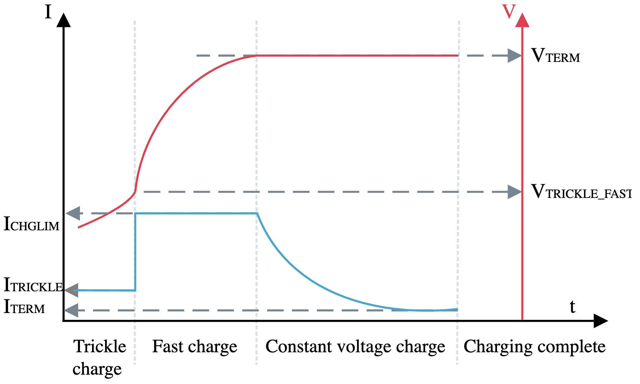
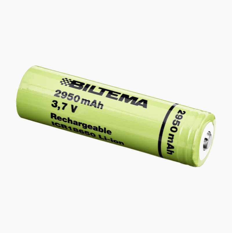
Li-Ion batteries
Most Li-Ion batteries can tolerate 1 C during fast charge
For Biltema 18650 cells: \(1\text{ C} = 2950\text{ mA}\) \(0.1\text{ C} = 295\text{ mA}\)
Most Li-Ion need to be charged to a termination voltage of 4.2 V
Too high termination voltage, or too high charging current can cause growth of lithium dendrites, that short + and -. Will end in flames. Always check manufacturer datasheet for charging curves and voltages
Battery charger - Inputs
Voltage above \(V_{TRICKLE}\)
Voltage close to \(V_{TERM}\)
If voltage close to \(V_{TERM}\) and current is close to \(I_{TERM}\), then charging complete
If charging complete, and voltage has dropped (\(V_{RECHARGE}\)), then start again
Battery charger - States
Trickle charge (0.1 C)
Fast charge (1 C)
Constant voltage
Charging complete

One way to draw FSMs - Graphviz
digraph finite_state_machine {
    rankdir=LR;
    size="8,5"

    node [shape = doublecircle, label="Trickle charger", fontsize=12] trkl;
    node [shape = circle, label="Fast charge", fontsize=12] fast;
    node [shape = circle, label="Const. Voltage", fontsize=12] vconst;
    node [shape = circle, label="Done", fontsize=12] done;

    trkl -> trkl [label="vtrkl = 0"];
    trkl -> fast [label="vtrkl = 1"];
    fast -> fast [label="vterm = 0"];
    fast -> vconst [label="vterm = 1"];
    vconst-> vconst [label="iterm = 0"];
    vconst-> done [label="iterm = 1"];
    done-> done [label="vrchrg = 0"];
    done-> trkl [label="vrchrg = 1"];

}
dot -Tpdf bcharger.dot -o bcharger.pdf
module bcharger( output logic trkl,
        output logic fast,
        output logic vconst,
        output logic done,
        input logic  vtrkl,
        input logic  vterm,
        input logic  iterm,
        input logic  vrchrg,
        input logic  clk,
        input logic  reset
                    );

   parameter TRLK = 0, FAST = 1, VCONST = 2, DONE=3;
   logic [1:0]                   state;
   logic [1:0]                   next_state;

   //- Figure out the next state
   always_comb begin
      case (state)
        TRLK: next_state = vtrkl ? FAST : TRLK;
        FAST: next_state = vterm ? VCONST : FAST;
        VCONST: next_state = iterm ? DONE : VCONST;
        DONE: next_state = vrchrg ? TRLK :DONE;
        default: next_state = TRLK;
      endcase // case (state)
    end
   //- Control output signals
   always_ff @(posedge clk or posedge reset) begin
      if(reset) begin
         state <= TRLK;
         trkl <= 1;
         fast <= 0;
         vconst <= 0;
         done <= 0;
      end
      else begin
         state <= next_state;
         case (state)
           TRLK: begin
              trkl <= 1;
              fast <= 0;
              vconst <= 0;
              done <= 0;
           end
           FAST: begin
              trkl <= 0;
              fast <= 1;
              vconst <= 0;
              done <= 0;

           end
           VCONST: begin
              trkl <= 0;
              fast <= 0;
              vconst <= 1;
              done <= 0;

           end
           DONE: begin
              trkl <= 0;
              fast <= 0;
              vconst <= 0;
              done <= 1;
           end
         endcase // case (state)
      end // else: !if(reset)
   end
endmodule

Synthesize FSM with yosys
dicex/sim/verilog/bcharger_sv/bcharger.ys
# read design
read_verilog -sv bcharger.sv;
hierarchy -top bcharger;

# the high-level stuff
fsm; opt; memory; opt;

# mapping to internal cell library
techmap; opt;
synth;
opt_clean;

# mapping flip-flops
dfflibmap  -liberty ../../../lib/SUN_TR_GF130N.lib

# mapping logic
abc -liberty ../../../lib/SUN_TR_GF130N.lib

# write synth netlist
write_verilog bcharger_netlist.v
read_verilog  ../../../lib/SUN_TR_GF130N_empty.v
write_spice -big_endian -neg AVSS -pos AVDD -top bcharger bcharger_netlist.sp

# write dot so we can make image
show -format dot -prefix bcharger_synth -colors 1 -width -stretch
clean
