cictikz
AI-driven TikZ circuit schematics
Domain libraries
Beyond the schematic vocabulary, the package ships
eleven domain libraries, inlined by wrap_body alongside
cictikz_lib (macro names are unique across all twelve).
Specimens below are auto-rendered with guessed arguments; macros
without an image only make sense composed into a larger figure.
boot — the bootstrapped switch
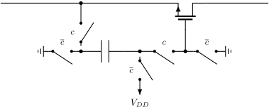
The bootstrapped switch, shared by l5_sw2 and l5_sw3. l5_sw2 shows one of them next to a bulk switched transmission gate; l5_sw3 shows two of them driving a differential pair with cross coupled dummies. It is the same drawing all three times, so it lives here and the figures inherit identical geometry. How it works. In phase c-bar the capacitor is strapped between ground and V_DD and charges to the supply, while the gate is held at ground and the switch is off. In phase c the bottom plate follows A and the top plate is handed to the gate, so V_GS = V_DD whatever A does. That is the point: the on resistance no longer depends on the signal. \bootBlockDn is the same block drawn below its rail rather than above it. l5_sw3 needs it: with both halves pointing the same way the lower network sits in the middle of the figure and the wires to the dummies have nowhere to run, which is what makes the original crowded. Every name is prefixed. Short generic names collide with LaTeX built-ins – \th is thorn – and the redefinition is fatal, not a warning.
bootSwH
\bootSwH{...}{...}{...}

bootSwHd
\bootSwHd{...}{...}{...}

bootSwD
\bootSwD{...}{...}{...}

bootSwU
\bootSwU{...}{...}{...}

bootGndL
\bootGndL{...}{...}

bootGndR
\bootGndR{...}{...}

bootGndD
\bootGndD{...}{...}

bootPort
\bootPort{...}{...}{...}
bootBlock
\bootBlock{...}
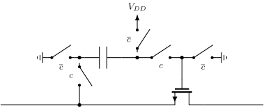
bootBlockDn
\bootBlockDn{...}
constellation — modulation constellations
Constellation diagrams for the modulation section of the radio chapter. Every one of these is the same picture with different dots on it: a real and an imaginary axis, tick marks at +/-1, and a symbol at each point the modulator can produce. Keeping the frame in one macro means the four diagrams are actually comparable, which is the whole reason the chapter shows them one after another. \constframe{
} draws the axes and their labels. \constsymbol{re}{im} marks one symbol. \constcircle{r} the unit circle, for the phase-only schemes.
constframe
\constframe{...}

constsymbol
\constsymbol{...}{...}

constcircle
\constcircle{...}
dacsm — DAC state machines
The bubble-and-arrow language the four l04_dac coding slides share: dac_bin_states, dac_bin_btran, dac_thermo_states and dac_thermo_tran. The originals draw plain circles with the code inside and straight arrows between them, with the two directions of a pair drawn side by side rather than as one double-headed arrow. \dacEdge offsets each arrow off the centre line so a pair reads as two arrows.
dacState
\dacState{...}{...}{...}

dacStateWide
\dacStateWide{...}{...}{...}

dacEdge
\dacEdge{...}{...}
dacArrow
\dacArrow{...}{...}
esd — ESD networks and zaps
Shared frame for the ESD build-up sequence in l02_esd. Four figures in the chapter are the same picture with more added each time: a chip outline with three rails brought out to pads, then one diode, then two, then the whole network with the grounded gate NMOS. They only teach anything if they are literally the same drawing, so the frame lives here and each figure adds its own devices. Coordinates: pads at x = 0, rails run to \esdRight. VDD at \esdVdd, the signal pin at \esdPin, VSS at zero. The band between VSS and the pin has to hold a device, the gate resistor beside it and a two line caption above it, which is what sets \esdPin. The hand drawing these figures replace put every device in that one band with the captions in a row above them, and that is worth keeping: it is what lets the eye read the network as one row of paths rather than four scattered symbols.
Constants: \esdVdd = 5.8, \esdPin = 3.4, \esdRight = 9.8, \esdLow = 1.7, \esdCap = 2.45
esdPadAt
\esdPadAt{...}{...}
esdPad
\esdPad{...}
esdframe
\esdframe
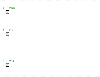
esdDiode
\esdDiode{...}{...}{...}{...}{...}

esdggn
\esdggn{...}{...}{...}{...}{...}{...}
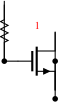
esdZapIn
\esdZapIn{...}
esdZapOut
\esdZapOut{...}

gmc — gm-C filter blocks
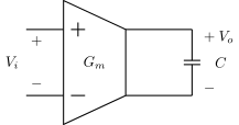
Shared pieces for the l04_afe Gm-C cell figures. l4_gmc, l4_gmc_diff, l4_gmc_diff1 and l4_gmc1st all draw the transconductor the same way the original artwork does: a trapezoid with a tall input edge carrying the two input terminals and a short output edge. They are consecutive slides making the same point four ways, so they have to be on one geometry. l4_gmc_diff and l4_gmc_diff1 differ only in the output terminal marks and in which way the two G_m V_i arrows point – that difference is the whole slide – so \gmcDiffFrame draws everything else and leaves those to the caller, the same way sc_lib’s \scIntroFrame does. Every name is prefixed and every macro name is letters only: TeX reads \gmcC1 as \gmcC followed by a stray 1, and fails at use rather than at definition. Computed coordinates are wrapped in braces, because TikZ scans a coordinate for its closing parenthesis and a ‘(‘ inside the expression ends it early.
Constants: \gmcW = 1.5, \gmcHi = 1.5, \gmcHo = 0.8
gmcBody
\gmcBody{...}{...}{...}
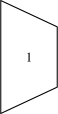
gmcBodyL
\gmcBodyL{...}{...}{...}
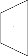
gmcPlus
\gmcPlus{...}{...}
gmcMinus
\gmcMinus{...}{...}
gmcVcap
\gmcVcap{...}{...}{...}

gmcHcap
\gmcHcap{...}{...}{...}

gmcDiffFrame
\gmcDiffFrame
mos — MOSFET cross-section cartoons
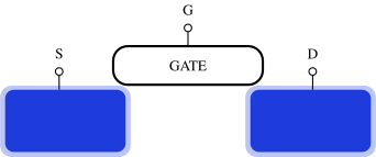
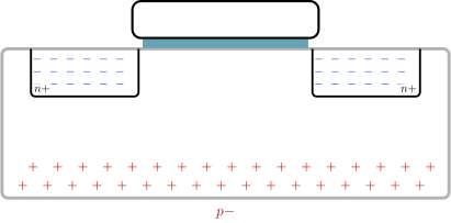
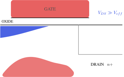
Shared pieces for the lr0_mosfet cross-section cartoons. Two families use this file:
- the field-effect intro (mosfet_off/subthreshold/strong_inversion…): white background, glowing blue n+ blocks, gate box, S/G/D terminals
- the carrier cartoons (accumulated/depleted/weakinv/vds_*): gray substrate, n+ boxes with blue minus signs, red plus signs in the p- bulk, teal oxide strip under the gate The colour language follows the original hand drawings: free electrons are blue, holes are red, the lecture prose (“imagine the free electrons as a blue fluorescent color”) depends on it.
fetblock
\fetblock{...}{...}

fetterminal
\fetterminal{...}{...}{...}

fetframe
\fetframe
eminus
\eminus{...}{...}

hplus
\hplus{...}{...}

efill
\efill{...}{...}

bulkframe
\bulkframe
neckrow
\neckrow{...}{...}

sideholes
\sideholes

bulkterminalgnd
\bulkterminalgnd{...}{...}{...}

drainzoomframe
\drainzoomframe
plane — s/z-plane diagrams
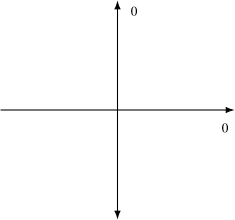
Shared pieces for the l05_sc s-plane and z-plane diagrams. l5_sdomain, l5_zdomain and l5_zunstable are the same pair of axes with different things marked on them, and the lecture walks from one to the next. Keeping the axes, the unit circle and the pole marker here means the three slides line up and a reader can see what changed. Pole and zero positions are given in units of the unit circle radius, so (0.5,0.3) means half a radius out. The macros scale by \planeR. Every name is prefixed: short generic names collide with LaTeX built-ins.
Constants: \planeR = 1.8, \planeXmax = 3.1, \planeYmax = 2.9, \planeMark = 0.17
planeAxes
\planeAxes{...}{...}
planeCircle
\planeCircle

planePole
\planePole{...}{...}{...}
planeZero
\planeZero{...}{...}{...}
rdac — resistor-DAC blocks
Shared pieces for the resistor-string DAC figures in l04_dac: dac_r_div, dac_r_div2 and dac_r_div2b are the same drawing with one, two and four resistors, so the switch and the terminal live here and the figures only place them. The originals draw the switches as bare NMOS symbols with the control on the gate stub above, so that is what \rdacSw draws: a device on a left-to-right path, which puts the gate on top.
rdacVgnd
\rdacVgnd{...}
rdacSpdt
\rdacSpdt{...}{...}{...}{...}
rdacAmp
\rdacAmp{...}{...}

rdacPort
\rdacPort{...}{...}{...}

rdacSw
\rdacSw{...}{...}{...}{...}

sc — switched-capacitor circuits
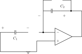
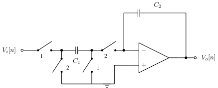
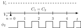
Shared pieces for the l05_sc switched-capacitor amplifier figures. l5_scintro1 and l5_scintro2 are the same circuit in its two clock phases, and the lecture’s whole charge-conservation argument works by comparing them. They therefore have to be drawn on identical geometry, which is what \scIntroFrame is for: it draws everything the two share and leaves the two switch positions to the caller, since those are exactly what differs. Every name is prefixed: short generic names collide with LaTeX built-ins. Names are letters only – TeX macro names cannot contain digits, so \scXc2 parses as \scXc followed by a 2 and fails at use, not at definition.
Constants: \scYgnd = 0, \scYin = 1.8, \scXota = 4.6, \scXctwo = 4.0, \scYctwo = 3.8, \scYsh = 4.8, \scXshr = 6.6, \scXout = 7.6, \scAmpYctwo = 3.8, \scAmpYrst = 4.9, \scAmpXrl = 4.9, \scAmpXrr = 6.9, \scWavT = 1.2, \scWavVi = 0.85, \scWavClk = -1.25, \scWavClkH = 0.55
scSwOpen
\scSwOpen{...}{...}

scSwClosed
\scSwClosed{...}{...}
scIntroFrame
\scIntroFrame
scSwH
\scSwH{...}{...}{...}

scSwV
\scSwV{...}{...}{...}

scPort
\scPort{...}{...}{...}
scAmpFrame
\scAmpFrame
scWaveEdge
\scWaveEdge{...}{...}{...}{...}

scWaveFrame
\scWaveFrame{...}
sfg — signal-flow and block diagrams
Shared pieces for the l04_afe signal flow graphs, l4_first_order and l4_biquad. The biquad is meant to read as the first-order graph with a second integrator added, so the summing node and the 1/s block have to be the same size and shape in both. They are the same size in the original artwork too. Names are prefixed and letters only, and computed coordinates are braced: TikZ scans a coordinate for its closing parenthesis, so a ‘(‘ inside an expression ends it early.
Constants: \sfgR = 0.25, \sfgBw = 1.0, \sfgBh = 0.65
sfgSum
\sfgSum{...}{...}

sfgBox
\sfgBox{...}{...}{...}

sfgDot
\sfgDot{...}{...}

sfgMix
\sfgMix{...}{...}

sfgAmp
\sfgAmp{...}{...}{...}

sfgAntenna
\sfgAntenna{...}{...}
sfgTall
\sfgTall{...}{...}{...}{...}{...}

spec — spectra sketches
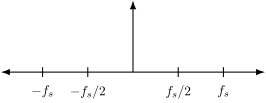
Shared pieces for the l05_sc sampling spectra. l5_sh, l5_shaaf and l5_subsample are the same drawing three times: no filter, an anti-alias low pass, and a bandpass around f_s. The slides make their point by looking alike, so the axis, the wanted signal and the tones all come from here and every figure inherits the same geometry. Every name is prefixed. \th is a LaTeX built-in and redefining it is a fatal error, so short generic names are not safe.
Constants: \specHalf = 1.2, \specXmax = 3.5, \specVh = 1.9, \specToneH = 1.05, \specSkirt = 0.20, \specYtop = 3.9, \specYbot = 0
specAxis
\specAxis{...}
specBump
\specBump{...}

specTone
\specTone{...}{...}{...}
specBand
\specBand{...}{...}{...}{...}

specBlock
\specBlock{...}{...}{...}

specWire
\specWire{...}{...}{...}
