Sky130nm tutorial
If you find an error in what I’ve made, then fork, fix lectures/lr0_tut1.md, commit, push and create a pull request. That way, we use the global brain power most efficiently, and avoid multiple humans spending time on discovering the same error.
- Create the IP
- The file structure
- Github setup
- Start working
- Draw Schematic
- Typical corner SPICE simulation
- All corners SPICE simulations
- Draw Layout
- Layout verification
- Extract layout parasitics
- Simulate with layout parasitics
- Make documentation
- Edit info.yaml
- Setup github pages
- Frequency asked questions
Status: 0.5
If the commands don’t work, then you have not installed the tools. Check The Tools chapter first.
Create the IP
I’ve made some scripts to automatically generate the IP.
To see what files are generated, see tech_sky130A/cicconf/lelo.yaml
cd aicex/ip
cicconf newip ex --project lelo --technology sky130A --ip  tech_sky130A/cicconf/lelo.yaml
The file structure
It matters how you name files, and store files. I would be surprised if you had a good method already, as such, I won’t allow you to make your own folder structure and names for things. I also control the filenames and folder structure because there are many scripts to make your life easier (yes, really) that rely on an exact structure. Don’t mess with it.
Github workflows
On github it’s possible use something called workflows to run things every time you push a new version. It’s really nice, since it can then check that your design is valid.
The workflows are defined below.
.github
   workflows
   docs.yaml # Generate a github page
   drc.yaml  # Run Design Rule Checks
   gds.yaml  # Generate a GDS file from layout
   lvs.yaml  # Run Layout Versus Schematic
             # and Layout Parasitic Extraction
Configuration files
Each IP has a few files that define the setup, you’ll need to modify at least
the README.md and the info.yaml.
 .gitignore  # files that are ignored by git
 README.md   # Frontpage documentation
 config.yaml # What libraries are used. Used by  cicconf
 info.yaml   # Setup names, authors etc
 media       # Where you should store images for documentation
 tech -> ../tech_sky130A  # The technology library
Design files
A “cell” in the open source EDA world should consists of the following files
- Schematic (.sch)
- Layout (.mag)
- Documenation (.md)
The files must have the same name, and must be stored in design/<LIB>/ as
shown below.
Note there are also two symbolic links to other libraries. These two libraries contain standard cells and standard analog transistors (ATR) that you should be using.
design
  LELO_EX_SKY130A
  LELO_EX.sch
  JNW_ATR_SKY130A -> ../../jnw_atr_sky130a/design/JNW_ATR_SKY130A
  JWN_TR_SKY130A -> ../../jnw_tr_sky130a/design/JNW_TR_SKY130A
For example, if the cell name was LELO_EX, then you would have
design/LELO_EX_SKY130A/LELO_EX.sch: Schematic (xschem)design/LELO_EX_SKY130A/LELO_EX.sym: Symbol (xschem)design/LELO_EX_SKY130A/LELO_EX.mag: Layout (Magic)design/LELO_EX_SKY130A/LELO_EX.md: Markdown documentation (any text editor)
All these files are text files, so you can edit them in a text editor, but mostly you shouldn’t (except for the Markdown)
Simulations
All simulations shall be stored in sim. Once you have a Schematic ready for
simulation, then
cd sim
make cell CELL=LELO_EX
This will make a simulation folder for you. Repeat for all your cells.
sim
  Makefile
  cicsim.yaml -> ../tech/cicsim/cicsim.yaml
The work
All commands (except for simulation), shall be run in the work folder.
In the work/ folder there are startup files for Xschem (xschemrc) and Magic (.magicrc).
They tell the tools where to find the process design kit, symbols, etc. At some point you probably
need to learn those also, but I’d wait until you feel a bit more comfortable.
work
 .magicrc
 Makefile
 mos.24bit.dstyle -> ../tech/magic/mos.24bit.dstyle
 mos.24bit.std.cmap -> ../tech/magic/mos.24bit.std.cmap
 xschemrc
Github setup
Create a repository on github.
The name of the repository that you make on GitHub has to be the same as what is written after <your username> in the last command below. In this example, that is lelo_ex_sky130a.
cd lelo_ex_sky130a
git remote add origin \
 git@github.com:<your username>/lelo_ex_sky130a.git
Start working
Edit README.md
Open README.md in your favorite text editor and make necessary changes.
Familiarize yourself with the Makefile and make
I write all commands I do into a Makefile. There is nothing special with a Makefile, it’s just what I choose to use 20 years ago. I’m not sure I’d choose something different now.
cd work
make
Take a look inside the file called Makefile.
Draw Schematic
The block we’ll make is a current mirror with a 1 to 4 scaling.
A schematic is how we describe the connectivity, and the types of devices in an analog circuit. The open source schematic editor we will use is XSchem.
Open the schematic:
xschem -b ../design/LELO_EX_SKY130A/LELO_EX.sch &
Add Ports
Add IBPS_5U and IBNS_20U ports, the P and N in the name signifies what transistor the current comes from. So IBPS must go into a diode connected NMOS, and N will be our output, and go into a diode connected PMOS somewhere else.
Add transistors
Use ‘I’ or ‘Shift+i’ (note the letter case) to open the library manager. Click the lelo_ex_sky130A/design
path, then JNW_ATR_SKY130A and select JNWATR_NCH_4C5F0.sym
The naming convention for these transistors is <number of contacts on
drain/source>C<times minimum gate length>F, so the number before the C is the width,
and the number before/after the F is the length. The absolute size does not matter for now.
Just think “4C5F0 is a 4 contact wide long transistor”, while a “4C1F2 is a 4
contact wide, short transistor”.
Select the transistor and press ‘c’ to copy it, while dragging, press ‘shift-f’ to flip the transistor so our current mirror looks nice. ‘shift-r’ rotates the transistor, but we don’t want that now.
Place two transistors for the output transistor, as shown in the figure below.
Press ESC to deselect everything
Select the input transistor, and change the name to ‘xo1’
Select the first output transistor, and change the name to ‘xo0[1:0]’. Using bus notation on the name will create 2 transistors.
Select the second output transistor and give it the name ‘xo1[1:0]’.
Select ports, and use ‘m’ to move the ports close to the transistors.
Press ‘w’ to route wires.
Use ‘shift-z’ and z, to zoom in and out
Use ‘f’ to zoom full screen
Remember to save the schematic

Netlist schematic
Check that the netlist looks OK
In work/
make xsch CELL=LELO_EX
cat xsch/LELO_EX.spice
Typical corner SPICE simulation
I’ve made cicsim that I use to run simulations (ngspice) and extract results
Setup simulation environment
Navigate to the lelo_ex_sky130a/sim/ directory.
Make a new simulation folder
cicsim simcell  LELO_EX_SKY130A LELO_EX \
    ../tech/cicsim/cell_spice/template.yaml
I would recommend you have a look at simcell_template.yaml file to understand what happens.
Familiarize yourself with the simulation folder
I’ve added quite a few options to cicsim, and it might be confusing. For reference, these are what the files are used for
| File | Description |
|---|---|
| Makefile | Simulation commands |
| cicsim.yaml | Setup for cicsim |
| summary.yaml | Generate a README with simulation results |
| tran.meas | Measurement to be done after simulation |
| tran.py | Optional python script to run for each simulation |
| tran.spi | Transient testbench |
| tran.yaml | What measurements to summarize |
The default setup should run, so
cd LELO_EX
make typical
Modify default testbench (tran.spi)
Delete the VDD source
Add a current source of 5uA, and a voltage source of 1V to IBNS_20U
IBP 0 IBPS_5U dc 5u
V0  IBNS_20U 0 dc 1
Save the current in V0 by adding i(V0) to the save statement in the testbench
Save the voltage by adding v(IBPS_5U) to the save statement
.save i(V0) v(IBPS_5U)
Modify measurements (tran.meas)
Add measurement of the current and VGS. It must be added between the “MEAS_START” and “MEAS_END” lines.
let ibn = -i(v0)
meas tran ibns_20u find ibn at=5n
meas tran vgs_m1 find v(ibps_5u) at=5n
Run simulation
make typical
and check that the output looks okish.
Try to run the simulation again
make typical
If everything works, then the simulation now should not be run. Every time
cicsim runs (provided the sha: True option is set in cicsim.yaml) cicsim will
compute a SHA hash of all files (stored in output_tran/.sha) that is
referenced in the tran.spi. Next time cicsim is run, it checks the hash’s and
does not re-run if there is no need (no files changed).
Sometimes you want to force running, and you can do that by
make typical OPT="--no-sha"
Often, it’s the measurement that I get wrong, so instead of rerunning simulation every time I’ve added a “–no-run” option to cicsim. For example
make typical OPT="--no-run"
will skip the simulation, and rerun only the measurement. This is why you should split the testbench and the measurement. Simulations can run for days, but measurement takes seconds.
Modify result specification (tran.yaml)
Add the result specifications, for example
ibn:
  src:
    - ibns_20u
  name: Output current
  min: -5%
  typ: 20
  max: 5%
  scale: 1e6
  digits: 3
  unit: uA

vgs:
  src:
    - vgs_m1
  name: Gate-Source voltage
  typ: 0.6
  min: 0.3
  max: 0.8
  scale: 1
  digits: 3
  unit: V
Re-run the measurement and result generation
make typical OPT="--no-run"
Open results/tran_Sch_typical.html
Check waveforms
You can either use ngspice, or you can use cicsim, or you can use something I don’t know about
Open the raw file with
cicsim wave output_tran/tran_SchGtKttTtVt.raw
Load the results, and try to look at the plots. There might not be that much interesting happening
Searching waveforms
On the left side of the window you’ll see a text box in the middle between the
filename, and the wave names. This is a regex search field, and you can easily
search for waveforms (like i(v0)) that you want to find.
Note that the search field uses regular expressions. If you don’t know regex, then it’s time to learn. I always use the perl regular expression variants.
For example, searching for “i(v0)” won’t acctually show anything, because the
() are special characters. “i(v0)” will find it though.
I could search for both ibps and v0 at the same time with ibps|i\(, so it’s
well worth learning.
A great resource is Mastering Regular Expressions
All corners SPICE simulations
Analog circuits must be simulated for all physical conditions, we call them corners. We must check high and low temperature, high and low voltage, all process corners, and device-to-device mismatch.
Remove Vh and Vl corners (Makefile)
For the current mirror we don’t need to vary voltage, since we don’t have a VDD.
Open Makefile in your favorite text editor.
Change all instances of “Vt,Vl,Vh” and “Vl,Vh” to Vt
Run all corners
To simulate all corners do
make typical etc mc
where etc is extreme test condition and mc is monte-carlo.
Wait for simulations to complete.
Get creative with python
Open tran.py in your favorite editor, try to read and understand it.
The name parameter is the corner currently running, for example tran_SchGtAmcttTtVt.
The measured outputs from ngspice will be added to tran_SchGtAmcttTtVt.yaml
Delete the “return” line.
Add the following lines (they automatically plot the current and gate voltage)
import cicsim as cs
fname = name +".png"
print(f"Saving {fname}")
cs.rawplot(name + ".raw","time","v(ibps_5u),i(v0)" \
  ,ptype="",fname=fname)
Re-run measurements to check the python code
make typical etc mc OPT="--no-run"
You’ll see that cicsim writes all the png’s. Check with ls -l output_tran/*.png.
You’ll also notice it will slow down the simulation, so maybe remove the lines
from tran.py again ;-)
Generate simulation summary
Run
make summary
Install pandoc if you don’t have it
Run
pandoc -s README.md -o README.html
to generate a HTML slideshow that you can open in browser. Open the HTML file.
Viewing results without GUI browser
If your on a system without a browser, or indeed a GUI, then it’s possible to view the results in the terminal.
Check if lynx is installed, if it’s not installed, then
On linux
sudo apt-get install lynx
On Mac
brew install lynx
Then
lynx README.html
Think about the results
From the corner and mismatch simulation, we can observe a few things.
- The typical value is not 20 uA. This is likely because we have a M2 VDS of 1 V, which is not the same as the VDS of M1. As such, the current will not be the same.
- The statistics from 30 corners show that when we add or subtract 3 standard deviation from the mean, the resulting current is outside our specification of +- 5 %.
Draw Layout
A foundry (the factory that makes integrated circuits) needs to know how we want them to create our circuit. So we need to provide them with a “layout”, the recipe, or instruction, for how to make the circuit. Although the layout contains the same components as the schematic, the layout contains the physical locations, and how to actually instruct the foundry on how to make the transistors we want.
Open Magic VLSI
cd work
magic ../design/LELO_EX_SKY130A/LELO_EX.mag
Now brace yourself, Magic VLSI was created in the 1980’s. For it’s time it was extremely modern, however, today it seems dated. However, it is free, so we use it.
Magic VLSI
Try google for most questions, and there are youtube videos that give an intro.
Default magic start with the BOX tool. Mouse left-click to select bottom corner, left-click to select top corner.
Press “space” to select another tool (WIRING, NETLIST, PICK).
Type “macro help” in the command window to see all shortcuts
| Hotkey | Function |
|---|---|
| v | View all |
| shift-z | zoom out |
| z | zoom in |
| x | look inside box (expand) |
| shift-x | don’t look inside box (unexpand) |
| u | undo |
| d | delete |
| s | select |
| Shift-Up | Move cell up |
| Shift-Down | Move cell down |
| Shift-Left | Move cell left |
| Shift-Right | Move cell right |
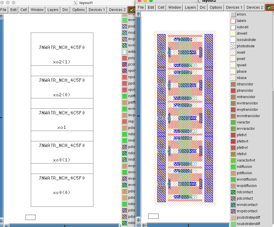
Add transistors
Open Cell -> Place Instance. Navigate to the right transistor.
Place it. Hover over the transistor and select it with ‘s’. Now comes a bit of tedious thing. Select again, and copy. It’s possible to align the transistors on-top of eachother, but it’s a bit finicky.
Place all transistors on top of each other as shown below in the picture.
Place devices
You will find that one of the more time consuming things with analog layout is to place the devices, and to follow the design rules from foundry. I detest tedious work. As such, I’ve tried for the past 25 years to simplify analog layout. I’ve not finished yet, but maybe you’ll find some of the scripts useful.
Note that the command below will override all your hard work ;-)
cd work
make xsch
cicpy sch2mag LELO_EX_SKY130A LELO_EX
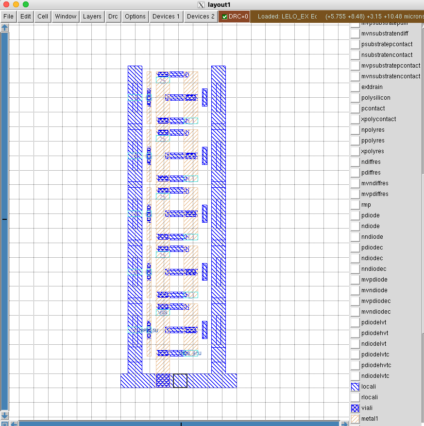
Add Ground
In the command window, type
see no *
see viali
see locali
see m1
see via1
see m2
Make a box around the layout by left cliking bottom left, and right clicking top right. Press ‘x’ to expand.
Change grid to 1 um. Set “Window->Snap to grid on”
Select a 1 um box below the transistors and paint the rectangle with locali (middle click on locali)
Change to the ‘wire tool’ with spacebar. Set “Window-> Snap to grid off”
Connect guard rings to ground.
Press the top transistor ‘S’ and draw all the way down to connect all of the transistors’ source terminals. Use ‘shift-right click’ to change layer down
Route Gates
Press “space” to enter wire mode. Left click on the top gate to start a wire, and right click to end the wire.
The drain of M1 transistor needs a connection from gate to drain. We do that for the middle transistor. Change to the box tool (spacebar a few times). Create a box that matches the locali. Connect the drain to the gate in locali.
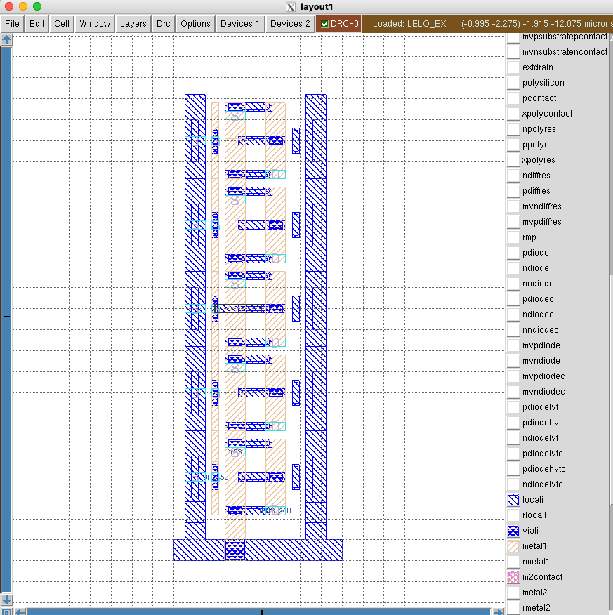
Drain of M2
Use the wire tool to draw connections for the drains.
To add vias you can do “shift-left click” to move up a metal, and “shift-right click” to go down.
It’s a very good idea to have direction rules for metal layers. I would recommend that you route metal1 vertical, metal2 horizontal, metal3 vertical etc. For locali it’s usually all over the place.

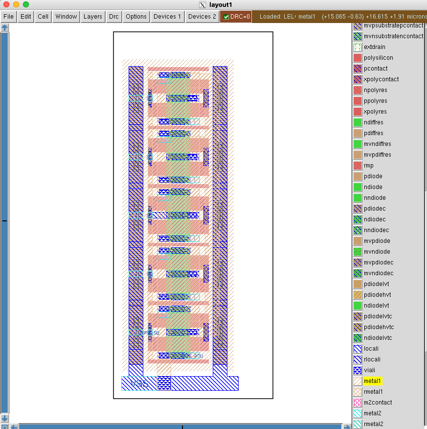
Add labels
All ports must be named (IBPS_5U, IBNS_20U, VSS). The cicpy script may add ports, but not necessarily where you want them.
Select a box on a metal, and use “Edit->Text” to add labels for the ports. Select the port button.
Layout verification
The DRC can be seen directly in Magic VLSI as you draw.
To check layout versus schematic navigate to work/ and do
make cdl lvs
Remember to save the layout first.
If you’ve routed correctly, then the LVS should be correct.
Extract layout parasitics
With the layout complete, we can extract parasitic capacitance.
make lpe
Check the generated netlist
cat lpe/LELO_EX_lpe.spi
Simulate with layout parasitics
Navigate to sim/LELO_EX. We now want to simulate the layout.
The default tran.spi should already have support for that.
Open the Makefile, and change
VIEW=Sch
to
VIEW=Lay
Typical simuation
Run
make typical
Corners
Navigate to sim/LELO_EX. Run all corners again
make all
Simulation summary
Open summary.yaml and add the layout files.
      - name: Lay_typ
        src: results/tran_Lay_typical
        method: typical
      - name: Lay_etc
        src: results/tran_Lay_etc
        method: minmax
      - name: Lay_3std
        src: results/tran_Lay_mc
        method: 3std
Run summary again
make summary
pandoc -s  README.md -o README.html
Open the README.html and have a look a the results. The layout should be close to the schematic simulation.
Make documentation
Make a file (or it may exists) design/LELO_EX_SKY130A/LELO_EX.md and add some
documentation of what you’ve made.
Add the simulation results to your git repository to keep track
git add sim/LELO_EX/results/*.html
git add sim/LELO_EX/README.md
Edit info.yaml
Finally, let’s setup the info.yaml so that all the github workflows run
correctly.
Mine will look like this.
You need to setup the url (probably something like <your username>.github.io)
to what is correct for you.
I’ve added the doc section such that the workflows will generate the docs.
The sim is to run a typical simulation.
library: LELO_EX_SKY130A
cell: LELO_EX
author: Carsten Wulff
github: wulffern
tagline: The answer is 42
email: carsten@wulff.no
url: wulffern.github.io
doc:
  libraries:
    LELO_EX_SKY130A:
      - LELO_EX
Setup github pages
Go to your GitHub repository (repo). Press Settings. Press Pages. Choose source under Build and Deployment -> GitHub Actions
Wait for the workflows to build. And check your github pages. Mine is https://wulffern.github.io/lelo_ex0_sky130a/.
Frequency asked questions
Q: My GDS/LVS/DRC action fails, even though it works locally.
Sometimes the reference to the transistors in the magic file might be wrong. Open the .mag file in a text editor and check. The correct way is
use JNWATR_NCH_4C5F0 JNWATR_NCH_4C5F0_0 ../LELO_ATR_SKY130A
It’s the last ../JNW_ATR_SKY130A that sometimes is missing.