Layout

The open source tools don't have any automatic analog layout. To my knowledge, there is no general purpose analog automagic layout anywhere in the world. It's an unsolved problem. Many have tried (including myself), but none have succeeded with a generic analog layout engine.

There are a few things, though, that could help you on the way.

1

Setup

I assume that you have the latest and greatest aicex\ip setup.

See SKY130NM Tutorial if aicex is unfamiliar.

Let's assume we use jnw_gr05_sky130a to test out our layout

cd aicex/ip/
cd jnw_gr05_sky130a
git checkout a1e3dfc324194729e042f5e653777b052759863b
cd work
2

CICPY

The first thing we need to do is to place all transistors. I do have a script to help. Install cicpy.

cd aicex/ip/cicpy
git checkout master
git pull 
python3 -m pip install -e .
cd ..
cd cicspi 
git checkout main 
git pull
python3 -m pip install -e .
3

Placement

To generate an initial placement we can do the command below. If a layout exists it will be overridden

cd jnw_gr05_sky130a/work 
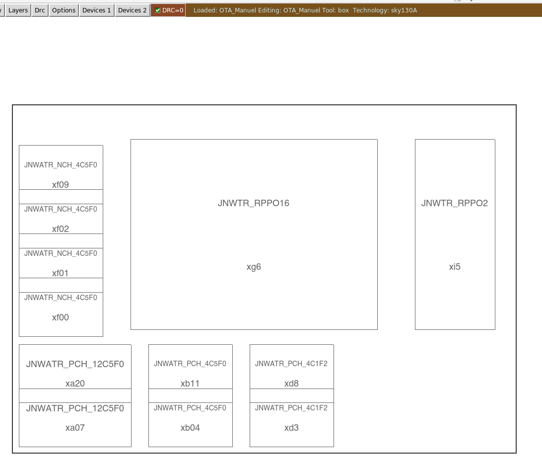
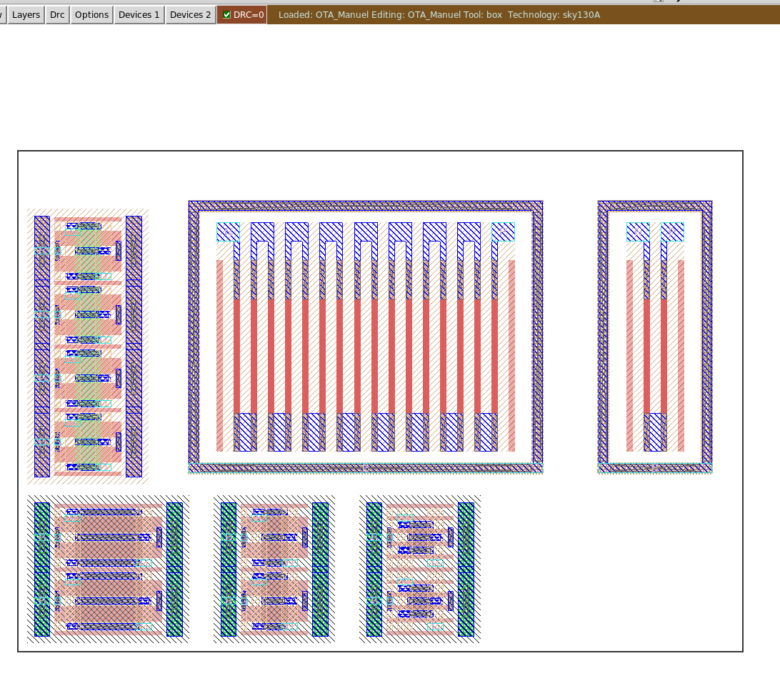
cicpy sch2mag JNW_GR05_SKY130A OTA_Manuel

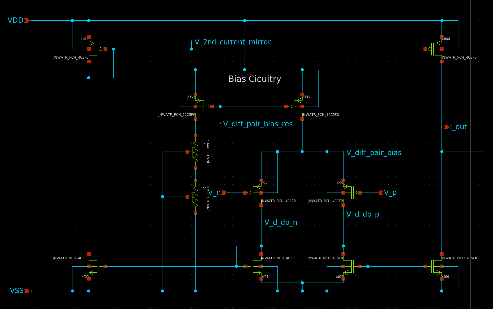
The layout engine has no idea what components belong together, for example, the current mirror below should have been placed together

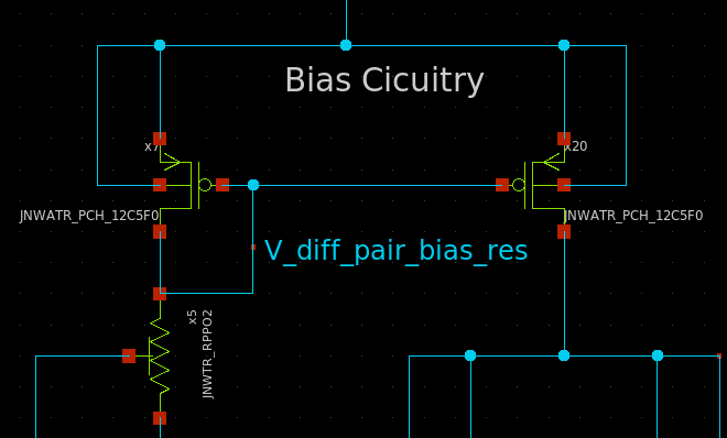
We can instruct the layout engine by adding a "group" name to the instance name. The instance name always starts with x<something><number> where the something can be nothing, or a group name (a,b, not a number).

The rules for placement are:

  1. Sort all instances by groups
  2. Sort all groups by instance name
  3. Place the first instance.
  4. For all instances: If the next instance has the same group, then add on top. Otherwise increment the x location.

As such, if I rename my instances, as shown below,

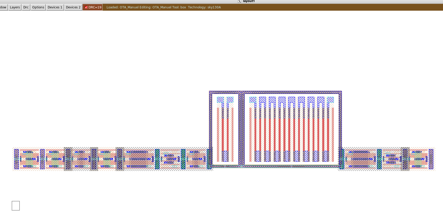
Then the layout becomes a bit better

cicpy sch2mag JNW_GR05_SKY130A OTA_Manuel --gbreak 3 --xspace 34000 --yspace 30000

The gbreak command inserts a "group break" after the fourth group, such that a new Y coordinate is selected.

The X and Y space is for the distance between groups. The unit is "Ångstrøm", so 1 um is 10 000 Å.
4

Summary

  • Layout is the final translation: from schematic to the polygons the fab will etch
  • Matching is geometry: symmetry, proximity, dummies, and common centroid where it counts
  • The parasitics are part of the circuit - extract and re-simulate before believing any layout
  • DRC and LVS are not suggestions: clean both, every time
5

Would you like to know more?

6