Carsten Wulff 2026
5
Why do we need voltage regulation
Introduction to linear regulators
Introduction to switched regulators
| Chemistry | Voltage [V] | |
|---|---|---|
| Primary Cell | LiFeS2 , Zn/Alk/MnO2 , LiMnO2 | 0.8 - 3.6 |
| Secondary Cell | Li-Ion | 2.5 - 4.3 |
| USB | - | 4.0 - 6.5 (20) |
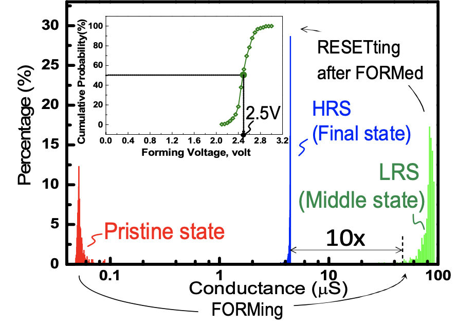
| Node [nm] | Voltage [V] |
|---|---|
| 180 | 1.8 |
| 130 | 1.5 |
| 55 | 1.2 |
| 22 | 0.8 |
| Voltage [V] |
|---|
| 5.0 |
| 3.0 |
| 1.8 |
| 1.2 |
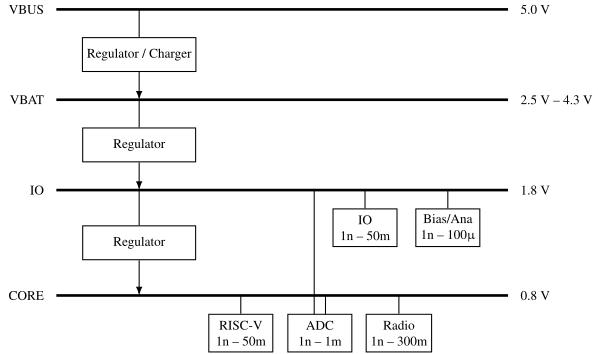
| Name | Voltage | Min [nA] | Max [mA] | PWR DR [dB] |
|---|---|---|---|---|
| VDD_VBUS | 5 | 10 | 500 | 77 |
| VDD_VBAT | 4 | 10 | 400 | 76 |
| VDD_IO | 1.8 | 10 | 50 | 67 |
| VDD_CORE | 0.8 | 10 | 350 | 75 |
| Parameter | Description | Unit |
|---|---|---|
| Load regulation | How much does the output voltage change with load current | V/A |
| Line regulation | How much does the output voltage change with input voltage | V/V |
| Power supply rejection ratio | What is the transfer function from input voltage to output voltage? The PSRR at DC is the line regulation | dB |
| Max current | How much current can be delivered through the pass-fet? | A |
| Quiescent current | What is the current used by the regulator | A |
| Settling time | How fast does the output voltage settle at a current step | s |
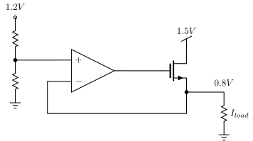
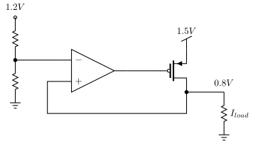
* Pass-fet
XM1 OUT G VDD VDD sky130_fd_pr__pfet_01v8
+ L=0.252 W=11.52 nf=2 ...  m=1000

* Reference
VREF VREF 0 dc 0.8

* OTA
BOTA G 0 V=(1 + tanh(-1000*(v(vref) -v(out) )))/2*{AVDD}

* Load cap
CL OUT 0 1u

* Current load
ILOAD OUT 0 pwl 0 0 1u 0 50u 0.5
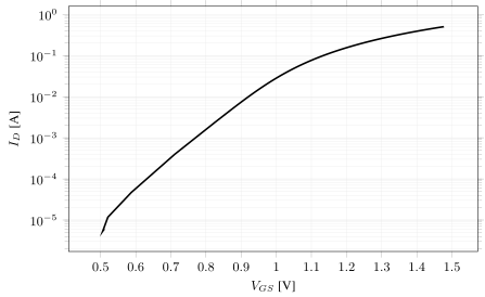
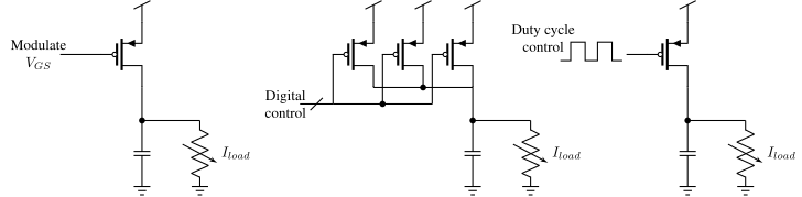
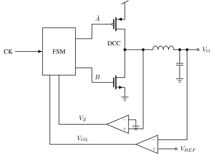
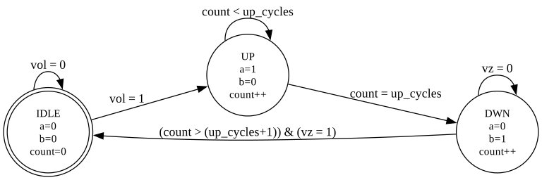
There is a big difference between the idea for a circuit, and the actual implementation. A real DC/DC implementation may seem overwhelming.
Just look at figure 7 in A 10-MHz 2–800-mA 0.5–1.5-V 90% Peak Efficiency Time-Based Buck Converter With Seamless Transition Between PWM/PFM Modes [@kim18]
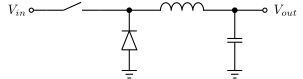
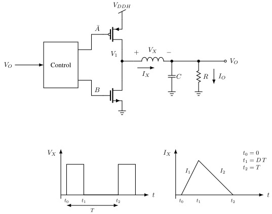
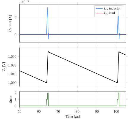
\[I_x(t) = \frac{1}{L} \int{V_x(t) dt}\]
\[V_o(t) = \frac{1}{C} \int{(I_x(t) - I_o(t))}dt\]
Jupyter PWM BUCK model - interactive - closed loop with type 3