The Project

1

A fantastic project that just might turn your world upside down, push you to re-evaluate your life choices, and stare briefly into the existential void… all while being deeply enjoyable and engaging! - Domen, AIC2025

2

The goal of the project is for you to experience a full mixed signal integrated circuit design, with the option of tapeout!

In 2025, two groups reached a tapeout of their design http://analogicus.com/jnw-tt-2025/ on the https://tinytapeout.com/chips/ttsky25a/ Tiny Tapeout shuttle.

3

The challenge

Design a temperature sensor

4

Systems-on-chip have complex regulator systems

5

Leakage current varies orders of magnitude over temperature


\[I_{leak} = I_0 e^{-V_{th}/n V_T} \left(1 - e^{-V_{ds}/V_T}\right)\]

6


7
  • Assume 1 pA at 25 C, and 1 nA at 125 C, per logic cell

  • Assume 100 million logic cells

  • Leakage at 25 C => 100 uA

  • Leakage at 125 C => 100 mA !!!

8

Why we would like to know the temperature on die

  • Assume we use 1 % of the load current for the regulator

  • At 25 C => 1 uA for LDO

  • At 125 C => 1 mA for LDO

It's insanely difficult to design a regulator that is efficient across the full range of leakage currents at any temperature.

It would be good if we could know temperature.

9

How to measure temperature?

10

The Project

11
12
Key Parameter Value Unit Description
Area Area < 15000 um^2 Must fit in 161 um x 111 um tiny tapeout 1x1 block, which is 17871 um^2
Tc Conversion time < 30 us Analog should only be active for one 32768 Hz period
Ts Sample period 100 ms One conversion every 100 ms, so 10 samples per second
Ileak Leakage current < 1 nA Typical temperature (25 C)
Iact Active current < 100 uA Typical temperature (25 C)
Iavg Average current < 50 nA Active current x conversion time/sample rate + leakage current. Typical temperature (25 C)
Kerrone Accuracy 0 - 70C +-10 C One temperature (25C) calibration
Kerrtwo Accuracy 0 - 70C +-5 C Two temperature (25C, 85C) calibration
13

Figure of Merit

A figure of merit allows us to compare circuits with different performance specifications, and try to answer the question. Which one is better?

The figure of merit for our temperature sensor will be

\[FOM = \left(\frac{T_{c}}{T_s}I_{act} + I_{leak}\right) K_{errtwo} \text{ [AK]}\]

14

Grade

Week Deadline Milestone Task Condition for more than 0 points Possible Points
4 2026-01-23 M0 Complete tutorial Link on blackboard 5
7 2026-02-13 M1 Design a circuit that can convert a temperature into a current and voltage Description of the circuit on github docs 5
10 2026-03-06 M2 Design a circuit that can convert a temperature into a frequency Description of the circuit on github docs. Demonstrate that it works 10
13 2026-03-27 M3 A verilog testbench that can convert a frequency into a digital value Description of the testbench on github docs. Demonstrate that it works 10
16 2026-04-17 M4 Layout of your circuit DRC/LVS/GDS passing on github 20
18 2026-05-01 M5 Individual report Uploaded to Inspera 48
? M6 Tapeout None 0
Coolness Extra points that I may choose to award 10
Total 108
15

Milestone 0: The tutorial

Goal: force you to install the tools, and get you started.

Follow Sky130nm Tutorial

Delivery: Submit link to your github repository on blackboard

For example, my repository: LELO_EX_SKY130A

The exercise will teach you the skills you need to do the project

16

Milestone 1: The bandgap

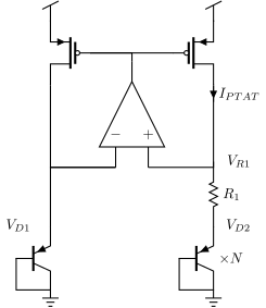
Goal: Create a circuit that can transform a temperature on the integrated circuit to a current proportional to temperature (PTAT), and a voltage complementary to temperature (CTAT).

Delivery: Link to your github repository with a description of how the bandgap works.

17

Milestone 2: The oscillator

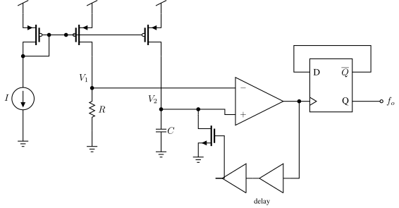
Goal: Use the PTAT current, and the CTAT voltage an create a oscillator.

Delivery Link to your github repository with description on how your oscillator works. There should be proof on how it works.

18

Milestone 3: The measurement

Goal: Measure the frequency of the oscillator.

Delivery: Link to your github repository where you describe how you measure the frequency of the oscillator.

19

Milestone 4 (Optional): The physical design

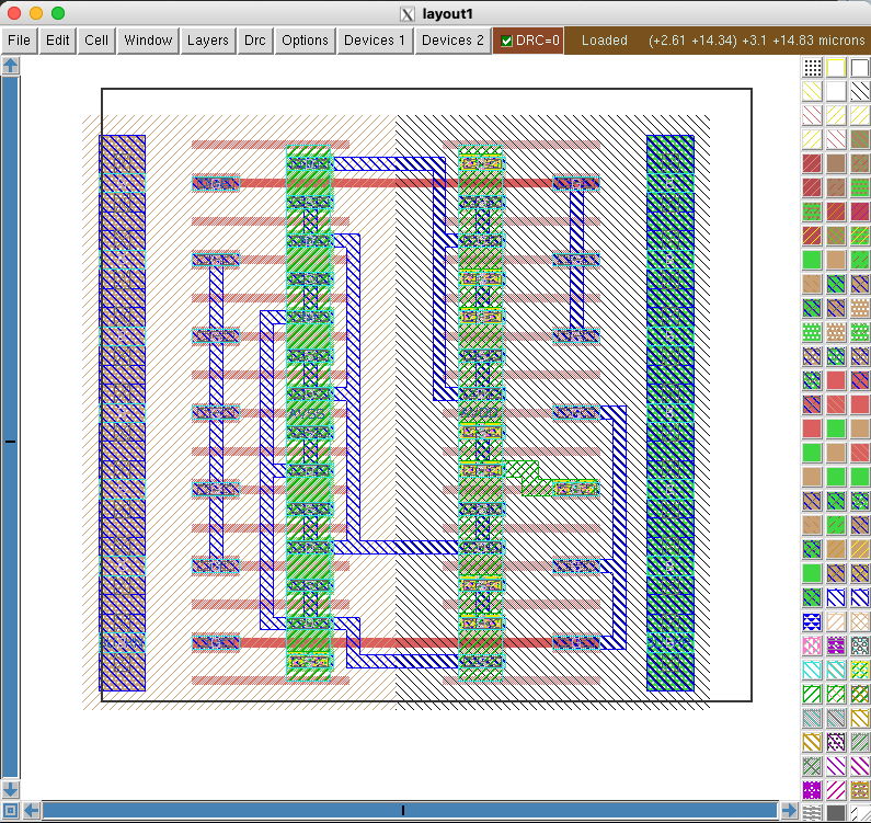
Goal: Do the physical layout of your oscillator, and prove that it still works with the layout parasitics.

Delivery: Link to your github repository with passing GDS, DRC, LVS actions.

20

Milestone 5: The Report

Goal: Write a report

Delivery: A PDF copy of the report in Inspera. You'll all write an individual report. The report shall be in the IEEE template.

See further details in https://analogicus.com/aic2026/how_to_write_a_project_report

21

Milestone 6 (Optional): The Tapeout

Target TTSKY26b tapeout (June 2026) on https://tinytapeout.com/chips/

Those students that follow the course at NTNU will be able to tapeout if the design is complete. I've gotten Nordic Semiconductor to sponsor the tapeout for 2026.

22

Thanks!

23

Summary

  • The project is the course: design a block in an open PDK, simulate it over corners, and document the evidence
  • Start from the template repositories and the cic flow on day one - infrastructure debt compounds
  • Work like an engineer: git for everything, scripts over clicks, claims backed by simulation
  • The report is the deliverable; the next chapter's writing guide is not optional reading
24

Would you like to know more?

25